Mitsubishi Lancer Evolution 7. Manual - part 363


  Index      Mitsubishi     Mitsubishi Lancer Evolution 7 - service repair manual


Search            


Content   ..  361  362  363  364   ..


Mitsubishi Lancer Evolution 7. Manual - part 363


SRS -

Troubleshooting

52B-17

<RS>

<Check the circuit between the SRS-ECU and clock

spring>

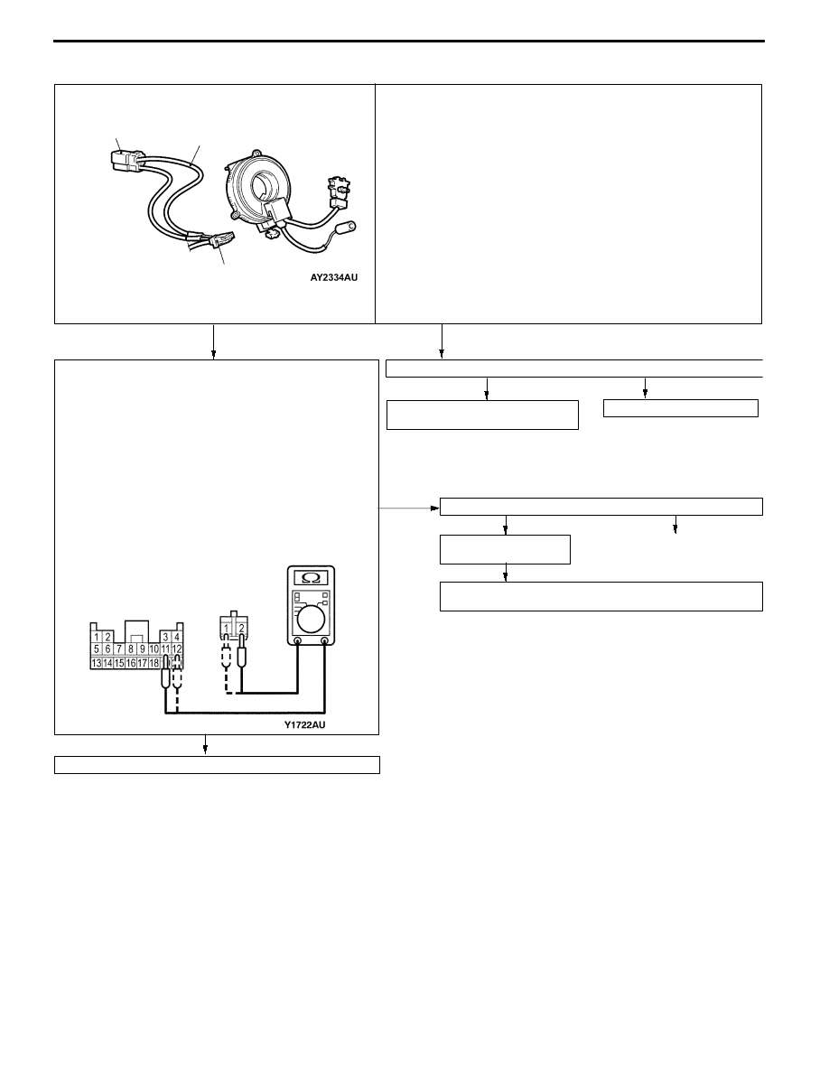
Measure at the SRS-ECU connector C-21 and the clock

spring connector C-204.
D

Disconnect the SRS-ECU connector C-21 and the clock

spring connector C-204 and measure at the harness side.

D

Continuity check between the following terminals
Connector C-21

Connector C-204

11

2

12

1

Caution

Do not directly insert a probe or other devices at the

front of the connector to avoid a possible decrease in

the contact pressure.

OK: Continuity (2Ω or less)

NG

Correct

Check connector: C-21, C-204

OK

Check the trouble

symptoms.

NG

Check the harness between the clock spring and the

SRS-ECU, and repair if necessary.

NG

Connector C-21

Connector C-204

<Clock spring check>
MUT-II self-diag code
D

Release the clock spring connector (2-pin) C-204.

D

Connect the dummy resistor (MB991865) to the resistor harness

(MB991866).

D

Insert the resistor harness

(MB991866) behind the harness side connector C-204.

Caution

Do not directly insert a probe or other devices at the front of the

connector to avoid a possible decrease in the contact pressure.

D

Connect the negative (-) terminal of the battery

D

Check the diagnosis code again after erasing the memory.

Is code No.22 output?

YES

Check the clock spring (Refer to P.52B-59.)

NO

YES

Replace the clock spring.

Replace the driver’s air bag module

(squib).

NO

Replace the SRS-ECU.

OK

Resistor harness

(MB991866)

Clock spring harness

side connector C-204

Dummy resistor

(MB991865)

resistance (3Ω)

SRS -

Troubleshooting

52B-18

<RS-II>

<Driver’s seat air bag module (squib) check>
MUT-II self-diag code
D

Disconnect the clock spring connector No.1 (connector connected with

the air bag module).

D

Connect the dummy resistor (MB991865) to the resistor harness

(MB991866).

D

Insert the resistor harness (MB991866) behind the clock spring

connector No.1.

Caution

Do not directly insert a probe or other devices at the front of the

connector to avoid a possible decrease in the contact pressure.

D

Connect the negative (-) terminal of the battery

D

Check the diagnosis code again after erasing the memory.

Is code No.22 output?

Dummy resistor

(MB991865)

resistance (3Ω)

1

YES

NO

Replace the steering wheel-driver’s air bag module assembly.

Resistor harness

(MB991866)

Go to Next Page

<Clock spring check>
MUT-II self-diag code
D

Release the clock spring connector (2-pin) C-204.

D

Connect the dummy resistor (MB991865) to the resistor harness

(MB991866).

D

Insert the resistor harness

(MB991866) behind the harness side connector C-204.

Caution

Do not directly insert a probe or other devices at the front of the

connector to avoid a possible decrease in the contact pressure.

D

Connect the negative (-) terminal of the battery

D

Check the diagnosis code again after erasing the memory.

Is code No.22 output?

YES

Replace the clock spring.

NO

Resistor harness

(MB991866)

C-204 clock spring

harness side connector

Dummy resistor

(MB991865)

resistance (3Ω)

SRS -

Troubleshooting

52B-19

<Check the circuit between the SRS-ECU and clock

spring>

Measure at the C-21 SRS-ECU connector and C-204 clock

spring connector.
D

Disconnect the SRS-ECU connector C-21 and the clock

spring connector C-204 and measure at the harness side.

D

Continuity check between the following terminals
C-21 connector

C-204 connector

11

2

12

1

Caution

Do not directly insert a probe or other devices at the

front of the connector to avoid a possible decrease in

the contact pressure.

OK: Continuity (2Ω or less)

NG

Correct

Check connector: C-21, C-204

OK

Check the trouble

symptoms.

NG

Check the harness between the clock spring and the

SRS-ECU, and repair if necessary.

YES

From Previous Page

NG

Connector C-21

Connector C-204

Replace the SRS-ECU.

OK

SRS -

Troubleshooting

52B-20

Code No.24 Front passenger’s air bag module (squib)

system

Possible Cause

This code is output when short circuit occurs between terminals of the

SRS-ECU front passenger’s air bag (squib) circuit.

However, SRS warning lamp goes out when a normal operation is resumed

(diagnosis code is not cleared.)

D

Connector engagement faulty or short bar faulty*

D

Short circuit between terminals of the front

passenger’s air bag (squib) circuit

D

Faulty connector

D

SRS-ECU inoperable

NOTE:

*: The connector of the squib circuit contains a short bar (short-circuiting the positive (+) cable and the

negative (-) cable to avoid an erroneous deployment caused by static electricity when a connector is

not connected). Thus, when a connector is connected, the short bar may not be released due to improper

engagement of the connector or faulty connector as shown in the illustration below. Disconnect the connector

as shown in the illustration below, then reconnect it. Check that a diagnosis code is output again after

erasing the memory. If the diagnosis code is not output, the above-mentioned code is output due to

improper engagement of the connector.

C-21

SRS-ECU

C-109

Front passenger’s air bag module


Content   ..  361  362  363  364   ..