Mitsubishi Lancer Evolution 7. Manual - part 352


  Index      Mitsubishi     Mitsubishi Lancer Evolution 7 - service repair manual


Search            


Content   ..  350  351  352  353   ..


Mitsubishi Lancer Evolution 7. Manual - part 352


EXTERIOR -

Outside Mirror

51-25

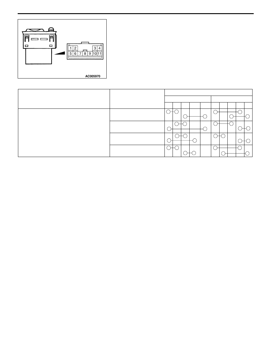
CONTINUITY INSPECTION OF POWER REMOTE

CONTROL MIRROR SWITCH<RS-II>

Switch

Switch position

Terminal number

p

Left

Right

1

6

9

10

11

1

2

3

6

9

Mirror adjustment switch

Up

Down

Left

Right

NOTES

52A-2

INTERIOR

CONTENTS

SPECIAL TOOL

3

. . . . . . . . . . . . . . . . . . . . . . . . . . . .

INSTRUMENT PANEL*

3

. . . . . . . . . . . . . . . . . . . . . .

FRONT FLOOR CONSOLE

10

. . . . . . . . . . . . . . . .

REAR FLOOR CONSOLE

12

. . . . . . . . . . . . . . . . . .

TRIMS

15

. . . . . . . . . . . . . . . . . . . . . . . . . . . . . . . . . . . .

HEADLINING

17

. . . . . . . . . . . . . . . . . . . . . . . . . . . . . .

SEAT

19

. . . . . . . . . . . . . . . . . . . . . . . . . . . . . . . . . . . . .

Front Seat

19

. . . . . . . . . . . . . . . . . . . . . . . . . . . . . . . . . .

Rear Seat

22

. . . . . . . . . . . . . . . . . . . . . . . . . . . . . . . . . .

SEAT BELT

25

. . . . . . . . . . . . . . . . . . . . . . . . . . . . . . .

Front Seat Belt

25

. . . . . . . . . . . . . . . . . . . . . . . . . . . . .

Rear Seat Belt

26

. . . . . . . . . . . . . . . . . . . . . . . . . . . . . .

WARNINGS REGARDING SERVICING OF SUPPLEMENTAL RESTRAINT SYSTEM (SRS) EQUIPPED VEHICLES
WARNING!
(1) Improper service or maintenance of any component of the SRS, or any SRS-related component, can lead to personal

injury ordeath to service personnel (from inadvertent firing of the air bag) orto the driver and passenger (from rendering

the SRS inoperative).

(2) Service or maintenance of any SRS component or SRS-related component must be performed only at an authorized

MITSUBISHI dealer.

(3) MITSUBISHI dealer personnel must thoroughly review this manual, and especially its GROUP 52B - Supplemental

Restraint System (SRS) before beginning any service or maintenance of any component of the SRS or any SRS-related

component.

NOTE
The SRS includes the following components: SRS-ECU, SRS warning lamp, air bag module, clock spring and interconnecting

wiring. Other SRS-related components (that may have to be removed/installed in connection with SRS service or maintenance) are

indicated in the table of contents by an asterisk (*).


Content   ..  350  351  352  353   ..