Mitsubishi Lancer Evolution 7. Manual - part 312


  Index      Mitsubishi     Mitsubishi Lancer Evolution 7 - service repair manual


Search            


Content   ..  310  311  312  313   ..


Mitsubishi Lancer Evolution 7. Manual - part 312


BASIC BRAKE SYSTEM -

On-vehicle Service

35A-15

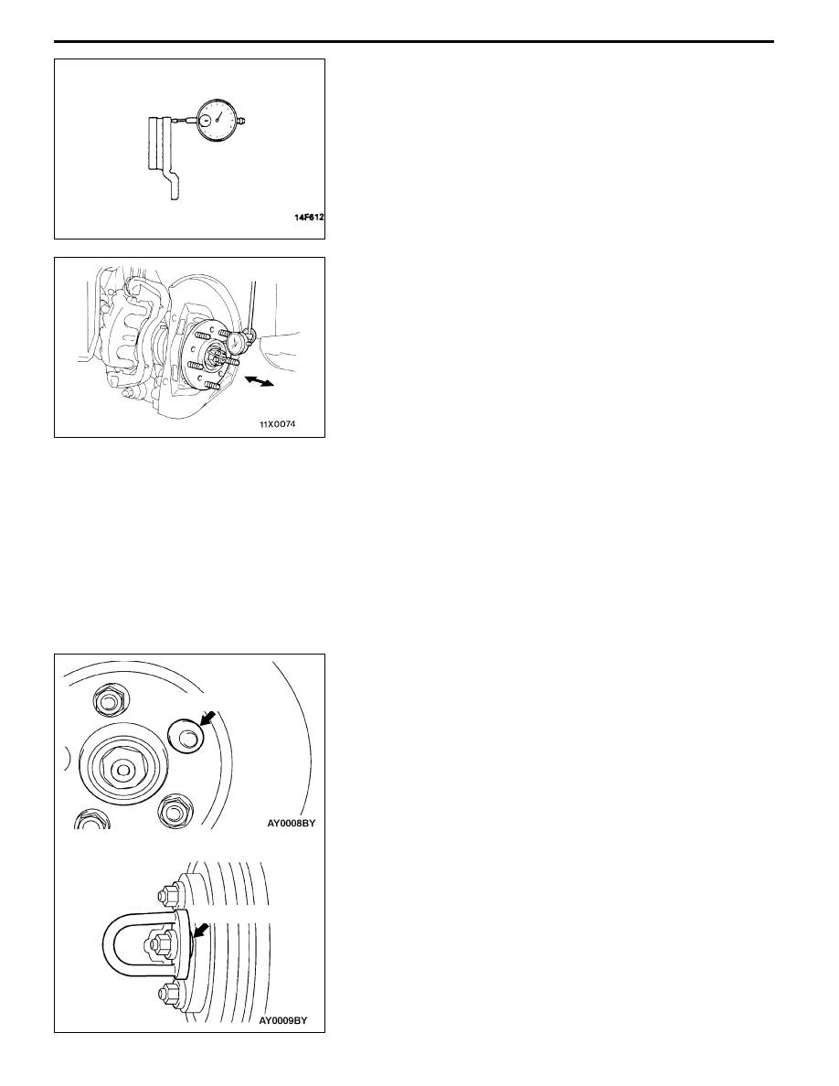
3. Place a dial gauge approximately 5 mm from the outer

circumference of the brake disc, and measure the run-out

of the disc.
Limit: 0.03 mm or less

4. If the brake disc run-out exceeds the limit, correct it as

follows:

(1) Chalk phase marks on the wheel stud and the brake

disc, which run-out is excessive.

(2) Remove the brake disc. Then place a dial gauge

as shown, and measure the wheel bearing axial play

by pushing and pulling the wheel hub.
Limit: 0.06 mm <Front>, 0.05 mm <Rear>

(3) If the wheel bearing axial play exceeds the limit,

disassemble the hub and knuckle assembly to check

each part.

(4) If the wheel bearing axial play does not exceed the

limit, dephase the brake disc and secure it. Then

recheck the brake disc run-out.

5. If the run-out cannot be corrected by changing the phase

of the brake disc, replace the brake disc or grind it with

the on-the-car type brake lathe ( “MAD, DL-8700PF” or

equivalent).

Caution

(1) After a new brake disc is installed, always grind

the brake disc with on-the-car type brake lathe.

If this step is not carried out, the brake disc run-out

exceeds the specified value, resulting in judder.

(2) When the on-the-car type lathe is used, first install

M12 flat washer on the stud bolt in the brake disc

side according to the figure, and then install the

adapter. If the adapter is installed with M12 flat

washer not seated, the brake disc rotor may be

deformed, resulting in inaccurate grinding.

(3) Grind the brake disc with all wheel nuts diagonally

and equally tightened to the specified torque 100

N·m. When all numbers of wheel nuts are not used,

or the tightening torque is excessive or not equal,

the brake disc rotor or drum may be deformed,

resulting in judder.

M12 flat washer

M12 flat washer

BASIC BRAKE SYSTEM -

Brake Pedal

35A-16

BRAKE PEDAL

REMOVAL AND INSTALLATION

Post-installation Operation

Brake Pedal Adjustment (Refer to P.35A-7.)

1

2

3

6

4

8

7

5

12 ± 2 N·m

14 ± 3 N·m

Removal steps

1. Harness connector

2. Stop lamp switch

3. Adjuster

4. Pedal stopper

5. Snap pin

6. Pin assembly

7. Pedal pad

"

AA 8. Brake pedal and pedal support

member

INSTALLATION SERVICE POINT

"

ABRAKE PEDAL AND PEDAL SUPPORT MEMBER

INSTALLATION

Tighten the brake booster mounting nuts (A), and then the

brake pedal mounting bolts (B).
NOTE

The pedal support member can not be positioned correctly

if the pedal mounting bolts (B) are tightened first as the their

holes are oblong holes.

A

A

B

B

BASIC BRAKE SYSTEM -

Brake Pedal/Proportioning Valve,

Master Cylinder and Brake Booster

35A-17

INSPECTION

STOP LAMP SWITCH CHECK
1. Connect an ohmmeter between the stop lamp switch

connector terminals.

2. There should be no continuity between the terminals when

the plunger is pushed in as shown. There should be

continuity when it is released.

PROPORTIONING VALVE, MASTER CYLINDER AND BRAKE

BOOSTER

REMOVAL AND INSTALLATION

Pre-removal Operation
D

Air Intake Hose and Air Cleaner Removal

<L.H. drive vehicles>

D

Strut Tower Bar Removal (Refer to GROUP 42.)

D

Brake Fluid Draining

Post-installation Operation
D

Brake Fluid Supplying and Air Bleeding

(Refer to P.35A-10.)

D

Brake Pedal Adjustment (Refer to P.35A-7.)

D

Air Intake Hose and Air Cleaner Installation

<L.H. drive vehicles>

D

Strut Tower Bar Installation (Refer to GROUP 42.)

5

10

11

3

12

4

14

15 ± 2 N·m

15 ± 2 N·m

22 ± 3 N·m

10 ± 2 N·m

13

2

8

14 ± 3 N·m

5

1

9

<R.H. drive vehicles>

9

<L.H. drive vehicles>

15 ± 2 N·m

5

Proportioning valves

<Vehicles without ABS>

6

7

30 ± 5 N·m

9

15

16 ± 1 N·m

<L.H. drive vehicles>

<R.H. drive vehicles>

9

15

16 ± 1 N·m

Vacuum hose, fitting

Specified Sealant: 3M ATD

Part

No.8661,

8663

or

equivalent

15

Fitting

4 mm

No continuity

Continuity

BASIC BRAKE SYSTEM -

Proportioning Valve, Master Cylinder

and Brake Booster

35A-18

Master cylinder removal steps

1. Clutch hose connection

2. Brake fluid level sensor connector

3. Reservoir cap assembly

4. Brake fluid level sensor

5. Brake pipe connection

6. Proportioning valve

<Vehicles without ABS>

7. O ring <Vehicles without ABS>

8. Master cylinder

Proportioning valve removal steps

<Vehicles without ABS>

5. Brake pipe connection

6. Proportioning valve

7. O ring

Brake booster removal steps

1. Clutch hose connection

2. Brake fluid level sensor connector

5. Brake pipe connection

8. Master cylinder

"

BA D Push rod protrusion amount check and

adjustment

"

AA 9. Vacuum hose

(With built-in check valve)

10. Snap pin

11. Pin assembly

12. Clevis

D

Remove A/C liquid pipe B

from the

retaining clip.

(Refer to GROUP 55A

- Refrigerant Line.)

13. Brake booster

14. Sealer

Fitting removal steps

"

AA 9. Vacuum hose

(With built-in check valve)

15. Fitting

INSTALLATION SERVICE POINTS

"

AVACUUM HOSE CONNECTION

Insert the vacuum hose to the brake booster with its paint

mark facing upward, and then secure the hose by using the

hose clip.

"

BPUSH ROD PROTRUSION AMOUNT CHECK AND

ADJUSTMENT

1. Measure dimension (A).

Standard value (A) : 8.98 - 9.23 mm
NOTE

When a negative pressure of 66.7 kPa is applied to the

brake booster, the push rod should protrude 10.27 – 10.53

mm.

Block gauge

Measuring distance A

A


Content   ..  310  311  312  313   ..