Mitsubishi Lancer Evolution 7. Manual - part 288


  Index      Mitsubishi     Mitsubishi Lancer Evolution 7 - service repair manual


Search            


Content   ..  286  287  288  289   ..


Mitsubishi Lancer Evolution 7. Manual - part 288


REAR AXLE -

Differential Carrier <Vehicles with mechanical LSD>

27B-37

BUSHING REPLACEMENT
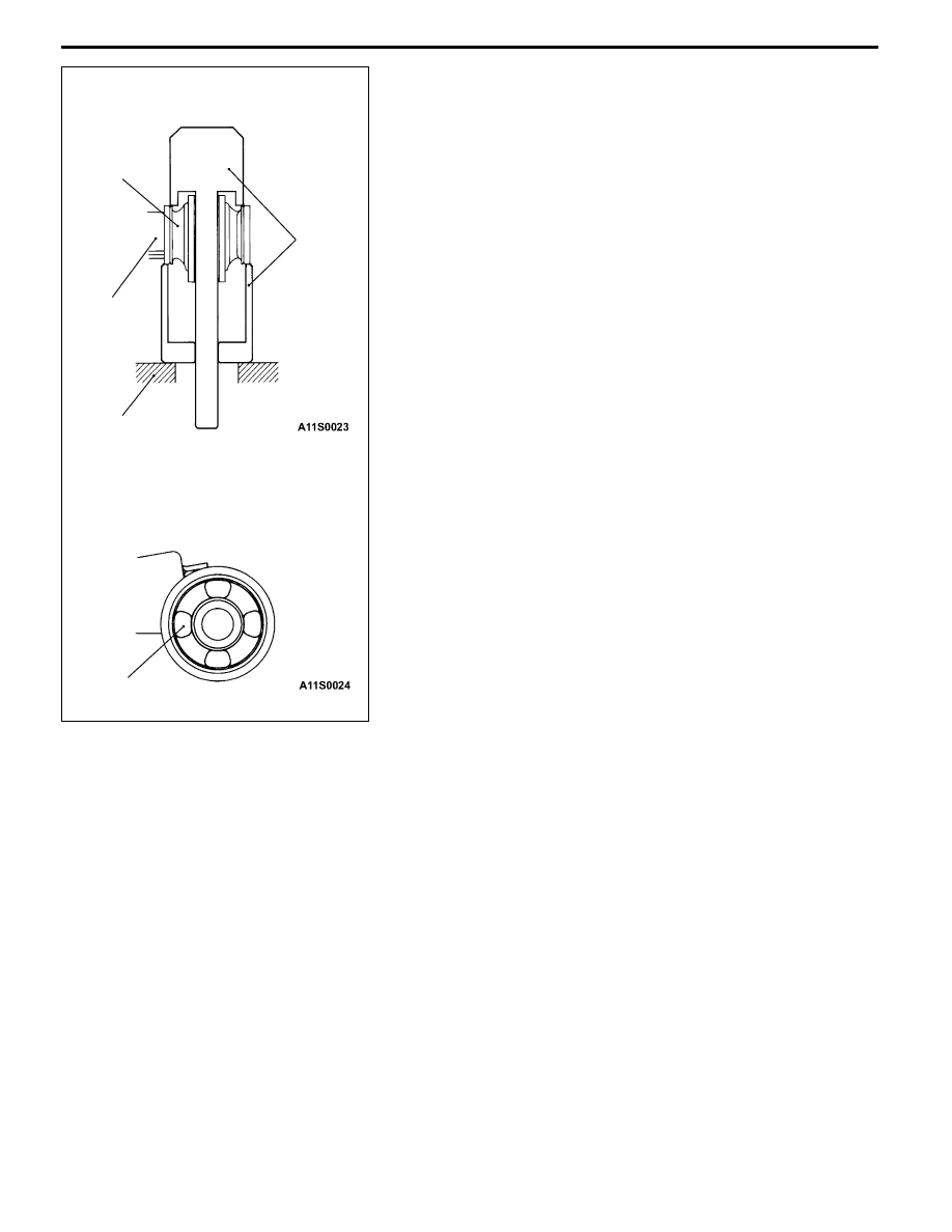
1. Remove and press fit the bush with special tool. (About

removal and press fitting the bush of the differential

support arm, refer to P. 27B-57.)

2. Press fit the bush so that the hollow of the bush is on

the position shown as the illustration.

3. Press fill the bush until the surface of the outer sleeve

of the bush, differential mounting bracket.

<Differential mount bracket>

MB990641

Bush

Differential

mount

bracket

Steel block

Hollow

REAR AXLE -

Differential Carrier <Vehicles with mechanical LSD>

27B-38

DISASSEMBLY

19

2

6

8

20

22

26

5

11

3

4

9

12

15

16

13

14

10

21

1

23

24

25

18

17

7

8 9

7

Disassembly steps

A

A"

D

Inspection before disassembly

1. Filler plug

2. Drain plug

3. Differential cover assembly

4. Vent plug

5. Bearing cap

A

B"

6. Differential case assembly

A

B"

7. Side bearing spacer

A

B"

8. Side bearing outer race

A

C"

9. Side bearing inner race

A

D"

10. Drive gear

11. Limited slip differential case assembly*

A

E"

12. Self-locking nut

13. Washer

A

F"

14. Drive pinion assembly

A

F"

15. Companion flange

16. Drive pinion front shim (For adjusting

preload of drive pinion)

17. Drive pinion spacer

A

G"

18. Drive pinion rear bearing inner race

19. Drive pinion rear shim (For adjusting

drive pinion height)

20. Drive pinion

A

H"

21. Oil seal

A

H"

22. Drive pinion front bearing inner race

A

H"

23. Drive pinion front bearing outer race

A

I"

24. Drive pinion rear bearing outer race

25. Oil seal

26. Differential carrier

REAR AXLE -

Differential Carrier <Vehicles with mechanical LSD>

27B-39

DISASSEMBLY SERVICE POINTS

A

AINSPECTION BEFORE DISASSEMBLY

1. Remove the cover.

2. Hold the special tool in a vise, and install the differential

carrier assembly to the special tool.

DRIVE GEAR BACKLASH
1. With the drive pinion locked in place, use a dial gauge

to measure the drive gear backlash in four or more places

on the drive gear.
Standard value: 0.11 - 0.16 mm

2. If the backlash is not within the standard value, adjust

the final drive gear backlash. (Refer to P.27B-49.)

3. After the adjustment, inspect the drive gear tooth contact.

DRIVE GEAR RUNOUT
1. Measure the drive gear runout at the shoulder on the

reverse side of the drive gear.
Limit: 0.05 mm

2. When runout exceeds the limit value, check for foreign

object between drive gear rear side and differential case,

or for loose drive gear installation bolts.

3. When check (2) gives normal results, reposition drive

gear and differential case and remeasure.

4. If adjustment is impossible, replace differential case, or

replace drive gear and pinion as a set.

DRIVE GEAR TOOTH CONTACT
Check the tooth contact of drive gear by following the steps

below.

1. Apply a thin, uniform coat of machine blue to both surfaces

of the drive gear teeth.

MB990909 and

MB991116

REAR AXLE -

Differential Carrier <Vehicles with mechanical LSD>

27B-40

2. Insert the brass between the differential carrier and the

differential case, and then rotate the companion flange

by hand (once in the normal direction, and then once

in the reverse direction) while applying a load to the drive

gear so that the revolution torque (approximate 2.5 -

3.0 N·m) is applied to the drive pinion.
Caution

If the drive gear is rotated too much, the tooth contact

pattern will become unclear and difficult to check.

3. Check the tooth contact condition of the drive gear and

drive pinion.

Standard tooth contact pattern

Problem

Solution

1

Narrow tooth side

2

Drive-side tooth surface (the

side applying power during

forward movement)

3

Wide tooth side

4

Coast-side tooth surface (the

side applying power during

reverse movement)

1

2

3

4

Tooth contact pattern resulting from

excessive pinion height

The drive pinion is positioned too far

from the centre of the drive gear.

1

2

3

4

Increase the thickness of the drive

pinion rear shim, and position the

drive pinion closer to the centre of the

drive gear. Also, for backlash adjust-

ment, position the drive gear farther

from the drive pinion.

1

2

3

4

Tooth contact pattern resulting from

insufficient pinion height

The drive pinion is positioned too

close to the centre of the drive gear.

1

2

3

4

Decrease the thickness of the drive

pinion rear shim, and position the

drive pinion farther from the centre of

the drive gear. Also, for backlash

adjustment, position the drive gear

closer to the drive pinion.

1

2

3

4

NOTE

Checking the tooth contact pattern is the way to

confirm that the adjustments of the pinion height

and backlash have been done properly. Continue

to adjust the pinion height and backlash until the

tooth contact pattern resembles the standard

pattern.

If, even after adjustments have been made, the

correct tooth contact pattern cannot be obtained,

it means that the drive gear and the drive pinion

have become worn beyond the allowable limit.

Replace the gear set.

MB990939


Content   ..  286  287  288  289   ..