Mitsubishi Lancer Evolution 7. Manual - part 286
REAR AXLE -
Drive Shaft
27B-29
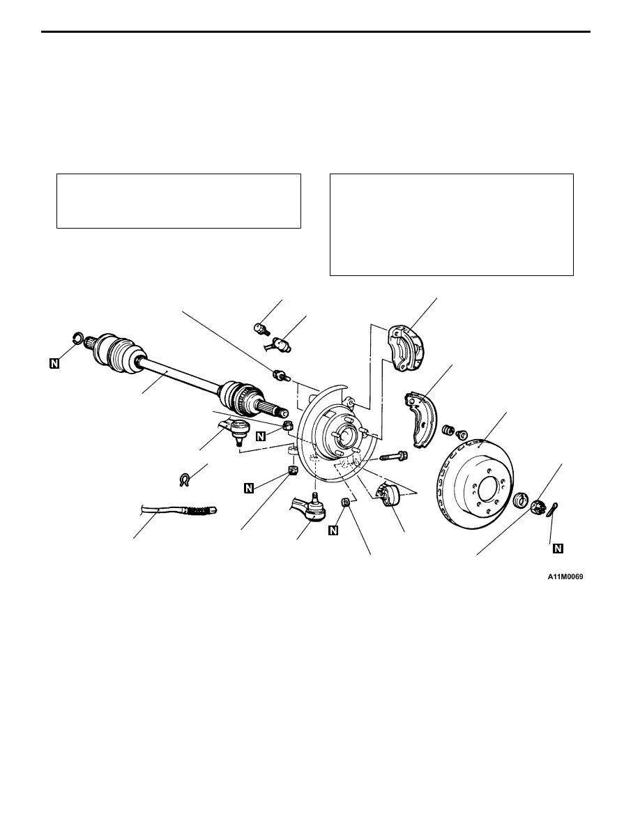
DRIVE SHAFT
REMOVAL AND INSTALLATION
Caution
1. If the vehicle is equipped with the Brembo disc brake, during maintenance, take care not to
contact the parts or tools to the caliper because the paint of caliper will be scratched. And
if there is brake fluid on the caliper, wipe out quickly.
2. With the part marked with *, first temporarily tighten it, then ground the vehicle and tighten
it to specification in unloaded condition.
Pre-removal Operation
D
Gear Oil Draining (Refer to P.27-17.)
D
Center Exhaust Pipe Removal (Refer to GROUP
15.)
Post-installation Operation
D
Press dust cover with a finger to check for crack
or damage in the dust cover.
D
Center Exhaust Pipe Installation (Refer to GROUP
15.)
D
Gear Oil Filling (Refer to P.27-17.)
D
Parking Brake Lever Stroke Check and Adjustment
D
Wheel Alignment Check and Adjustment (Refer to
GROUP 34 – On-vehicle Service.)
4
1
3
7
6
5
10
2
8
9
11
12
225 ± 25 N·m
54 ± 5 N·m
88 ± 10 N·m*
81 ± 6 N·m*
81 ± 6 N·m
25 ± 6 N·m
Removal steps
A
A"
1. Rear brake caliper
2. Rear brake disc
3. Parking brake shoe & lining assembly
(Refer to GROUP 36 - Parking Brake
Drum.)
4. Clip
5. Parking brake cable connection
6. Split pin
A
B" "BA 7. Drive shaft nut
8. Vehicle speed sensor<Vehicles with
ABS or ACD>
9. Knuckle and trailing arm connection
10. Knuckle and lower arm connection
11. Knuckle and toe-control arm connec-
tion
A
C" "AA 12. Rear drive shaft assembly