Mitsubishi Lancer Evolution 7. Manual - part 284


  Index      Mitsubishi     Mitsubishi Lancer Evolution 7 - service repair manual


Search            


Content   ..  282  283  284  285   ..


Mitsubishi Lancer Evolution 7. Manual - part 284


REAR AXLE -

On-vehicle Service

27B-21

5. Operate the MUT-II, drive the torque transfer differential

(item No.06 and 07) forcibly.
NOTE

(1) Drive the clutch operating mode forcibly for 1 minutes,

release the operation automatically. Drive can also

be cleared forcibly using the Clear key of MUT-II.

(2) If the hydraulic unit function has been stopped by

fail-safe, the torque transfer differential cannot be

forcibly driven.

6. Operating the MUT-II, by service data (item no.07 and 08),

check the condition of the wheel speed below.

<Driving item No.06 forcibly>

The left rear wheel is faster 2km/h than right rear wheel.

<Driving item No.07 forcibly>

The right rear wheel is faster 2km/h than left rear wheel.
NOTE

If the above are not satisfied, check the oil pressure as

the system may be faulty.

OIL PRESSURE CHECK

1. Lift up the vehicle.

2. Set the MUT-II to the 16-pin diagnosis connector.

Caution

Turn the ignition switch to the LOCK (OFF) position

before connecting or disconnecting the MUT-II.

3. Turn the ignition switch to ON.

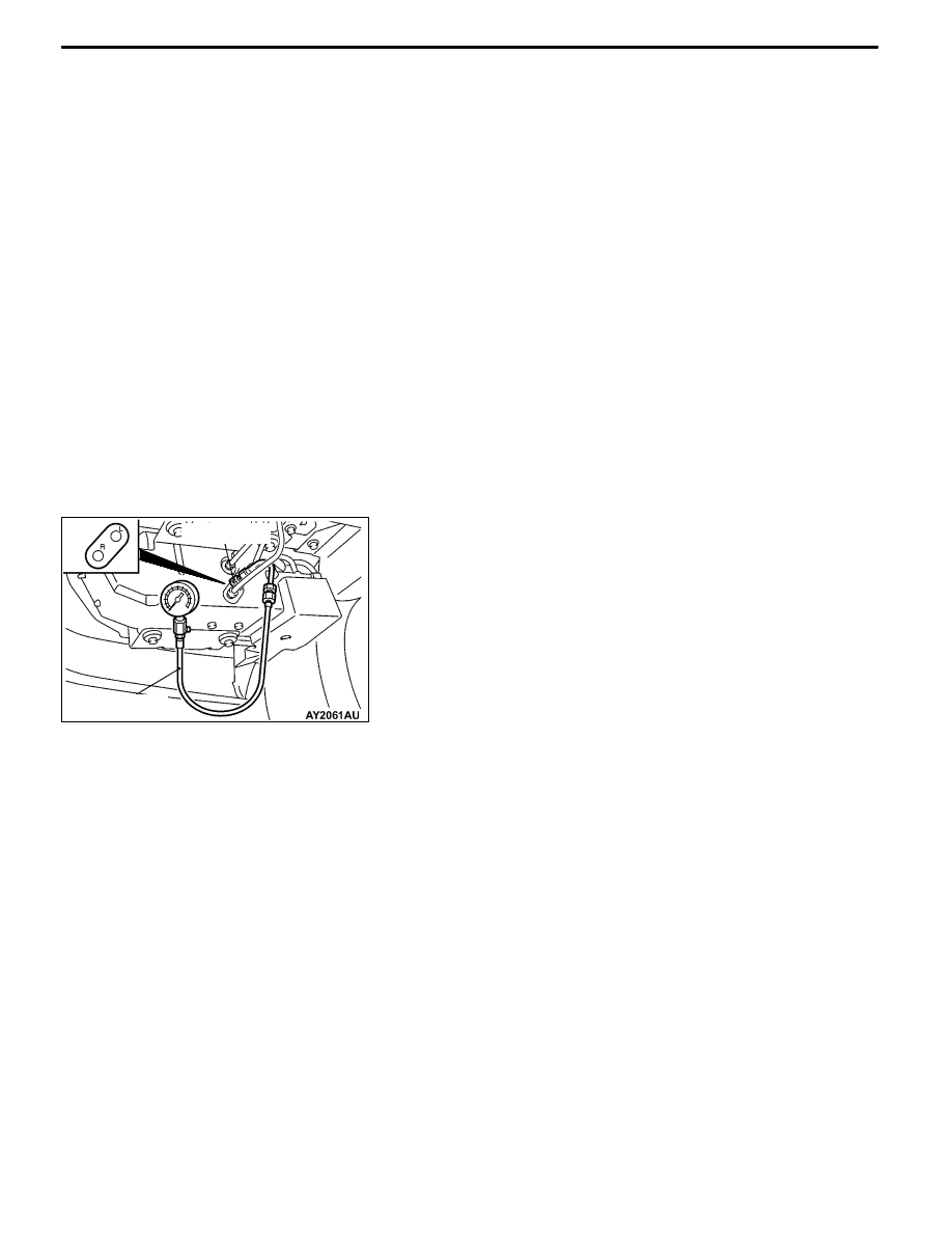
4. Disconnect the hydraulic unit and the hydraulic unit hose

assembly, connect the special tool to L port, put the lid

to R port or connect the hydraulic unit hose assembly

disconnected from L port to R port.

5. Operating the MUT-II, drive the hydraulic unit forcibly

(item No.02).
NOTE

(1) Drive the operation check mode of the clutch left

side for 1 minutes, release the operation automatically.

Drive can also be cleared forcibly using the Clear

key of MUT-II.

(2) If the function has been stopped by fail safe, the

hydraulic unit cannot be cleared forcibly.

6. Check that the generated oil pressure of the hydraulic

unit satisfies the standard value.
Standard value: 0.9 – 1.1 MPa
Caution

While the oil pressure is checked, add fluid as

necessary to ensure that it is left in the oil reservoir

during the entire procedure.

7. Check the oil pressure of the clutch right side following step

4 through 6. Connect the special tool to R port, put the lid

to L port or hydraulic unit hose assembly disconnected

from R port to L port, use the MUT-II drive item No.07

(operation check mode of clutch right side) forcibly.

MD998330

MB991705

REAR AXLE -

On-vehicle Service

27B-22

8. If the measured value exceeds the standard value, replace

the hydraulic unit.

9. Connect the hydraulic unit and the hydraulic unit hose

assembly, and connect the torque transfer differential and

hydraulic unit hose assembly, tighten the flare nut in

specified torque.
Tightening torque: 34 ± 5 N·m (Thread is not lubricated)

26 ± 4 N·m (Thread is lubricated)

10. Supply the specified fluid up to the MAX level of the

oil reservoir, and bleed.
Specified fluid: ATF-SP III

Quantity: 1 L

WHEEL BEARING AXIAL PLAY CHECK

1. Remove the brake caliper and brake disc.

2. Check the bearing’s axial play.

Place a dial gauge against the hub surface; then move

the hub in the axial direction and check whether or not

there is axial play.
Limit: 0.05 mm

3. If the axial play exceeds the limit, the castle nut should

be tightened to the specified torque 225 ± 25 N·m and

check the axial play again.

4. Replace the rear hub assembly if an adjustment cannot

be made to within the limit.

WHEEL BEARING ROTARY-SLIDING

RESISTANCE CHECK

1. Remove the brake caliper and brake disc.

2. After turning the hub a few times to seat the bearing,

wind a rope around the hub bolt and turn the hub by

pulling at a 90_ angle with a spring balance. Measure

to determine whether or not the rotary-sliding resistance

of the rear hub is at the limit value.
Limit: 22 N or less

REAR AXLE -

On-vehicle Service

27B-23

3. If the limit value is exceeded, loosen the flange nut and

then tighten it to the specified torque 225 ± 25 N·m and

check the rear hub rotary sliding resistance again.

4. Replace the rear hub assembly if an adjustment cannot

be made to within the limit.

HUB BOLT REPLACEMENT

1. Remove the brake caliper and brake disc.

2. Use the special tools to remove the hub bolts.

NOTE

To retain a space for removing the hub bolts, remove

near the retainer spring mounting position.

3. Install the plain washer to the new hub bolt, and install

the bolt with a nut.

DIFFERENTIAL CARRIER OIL SEAL

REPLACEMENT

Differential part
1. Remove the drive shaft. (Refer to P. 27B-29.)

2. Remove the oil seal from the differential carrier.

3. Using the special tool, drive a new oil seal all the way

into position.

4. Coat the oil seal lips and the drive shaft surface in contact

with the oil seal with multi-purpose grease.

5. Replace the drive shaft circlip with a new one and mount

the drive shaft to the differential carrier. (Refer to P.

27B-29.)

6. Check for correct wheel alignment. (Refer to GROUP

34 – On-vehicle Service.)

MB991618

MB990767

Plain

washer

MB990767

MB990938

MB991115

REAR AXLE -

On-vehicle Service

27B-24

Torque transfer mechanism part
1. Remove the drive shaft. (Refer to P. 27B-29.)

2. Remove the oil seal from the differential carrier.

3. Using the special tool, drive a new oil seal all the way

into position.

4. Coat the oil seal lips and the drive shaft surface in contact

with the oil seal with the specified grease.
Specified grease: Vaseline

5. Replace the drive shaft circlip with a new one and mount

the drive shaft to the differential carrier. (Refer to P.

27B-29.)

6. Check for correct wheel alignment. (Refer to GROUP

34 – On-vehicle Service.)

ACTION WHEN BATTERY RUNS OUT

When the engine is started using a booster cable where the

battery has completely run down and you attempt to start

the vehicle without waiting for the battery to recover a certain

charge, the engine can misfire and you just cannot start to

move it. In such cases, charge the battery sufficiently; or,

remove the AYC battery cable from the battery fuse assembly

to make AYC inactive before attempting to start the vehicles.

When the battery cable is removed, the ACD mode indicator

lamp lights up. After the battery has been recharged, fit the

battery cable back again and start the engine to ensure that

the ACD mode indicator lamp is off.

MD998829

MD998813

MD998812

Battery fuse assembly

Battery cable

for AYC


Content   ..  282  283  284  285   ..