Mitsubishi Lancer Evolution 7. Manual - part 263
MANUAL TRANSMISSION OVERHAUL -
Transmission
22B-17
29
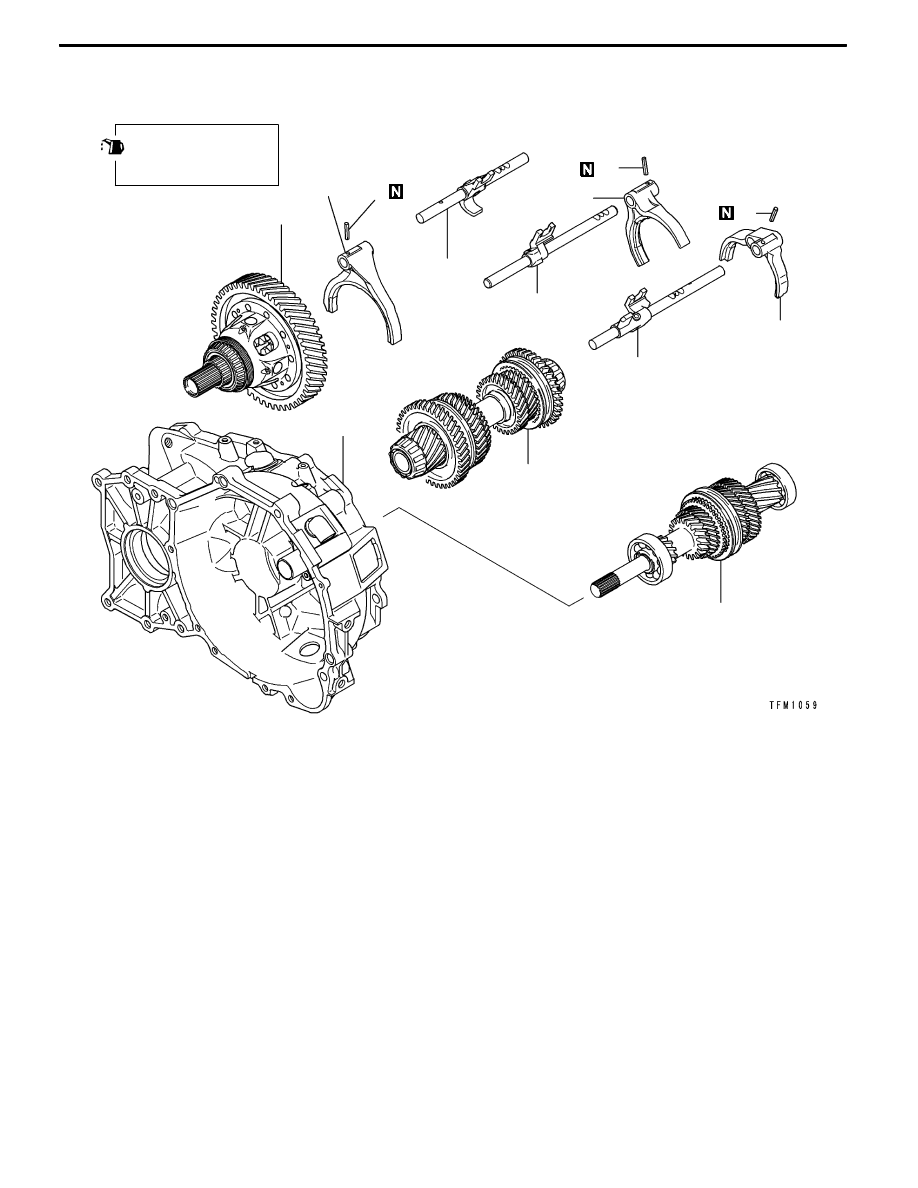
Apply gear oil on
all sliding sections
before installing.
36
32
30
28
35
38
37
39
27
34
33
31
Disassembly steps
"
CA 27. Spring pin
28. 1st-2nd speed shift rail
29. 1st-2nd speed shift fork
"
CA 30. Spring pin
A
A" "CA 31. Spring pin
A
B" "BA 32. 3rd-4th speed shift rail
A
B" "BA 33. 3rd-4th speed shift fork
A
B" "BA 34. 5th-reverse speed shift rail
A
B" "BA 35. 5th-reverse speed shift fork
A
C" "AA 36. Center differential
A
C" "AA 37. Output shaft
A
C" "AA 38. Input shaft
39. Clutch housing