Mitsubishi Lancer Evolution 7. Manual - part 252


  Index      Mitsubishi     Mitsubishi Lancer Evolution 7 - service repair manual


Search            


Content   ..  250  251  252  253   ..


Mitsubishi Lancer Evolution 7. Manual - part 252


MANUAL TRANSMISSION - Troubleshooting <ACD>

22A-31

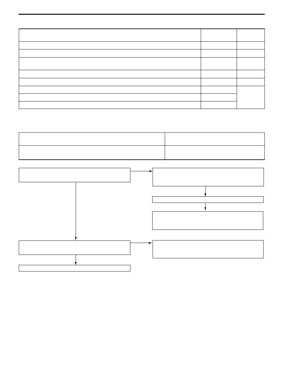
INSPECTION CHART FOR TROUBLE SYMPTOMS

Trouble symptom

Inspection

procedure No.

Reference

page

No communication possible between MUT-II and all systems.

1

22A-31

No communication possible between MUT-II and 4WD-ECU.

2

22A-32

ACD mode indicator lamp does not light up when the ignition switch is set to ”ON“

(engine is stopped).

3

22A-33

More than two ACD mode indicator lamps remain lit even after the engine is started

4

22A-34

The ACD does not operate (no diagnostic code).

5

22A-34

The AYC does not operate (no diagnostic code).

6

Refer

to

GROUP

The rear tire sounds when turning at low speed corners (vehicle slows down)

7

GROUP

27B.

Noise is produced from the torque transfer differential during turning.

8

27B.

INSPECTION PROCEDURES FOR TROUBLE SYMPTOMS

Inspection procedure 1

No communication possible between MUT-II and all

systems.

Probable cause

The diagnosis connector power supply circuit, earth circuit, or MUT-II may be

faulty.

D

Diagnostic connector fault

D

Harness or connector fault

D

MUT-II fault

OK

NG

NG

Check the harness between the fusible link No.1 and

diagnosis connector.
D

Check for open circuit or damage of the power line.

NG→Repair

OK

Check the trouble symptoms.

Measure at diagnosis connector C-22.
D

Voltage between terminal 16 and body earth

OK: System voltage

NG

Check the following connectors:

<L.H. drive vehicles> C-22, C-213, C-211, C-132

<R.H. drive vehicles> C-22, C-213, C-211, C-35, C-132

NG→Repair

Check the harness between the body earth and diagnosis

connector.
D

Check for open circuit and damage of the earth line.

NG→Repair

OK

Replace the MUT-II.

Measure at diagnosis connector C-22.
D

Resistance between terminals 4 and 5 and body earth.

OK: 2 Ω or less

MANUAL TRANSMISSION - Troubleshooting <ACD>

22A-32

Inspection procedure 2

No communication is possible between the MUT-II and

4WD-ECU.

Probable cause

The diagnostic output circuit, 4WD-ECU power supply circuit, earth circuit, or

4WD-ECU may be faulty.

D

Harness or connector fault

D

4WD-ECU fault

NG

OK

OK

NG

OK

OK

NG

OK

OK

NG

NG

NG

Check the trouble symptoms.

Check the harness between the 4WD-ECU and earth.
D

Check for open circuit and damage of the earth line.

NG→Repair

Check the following connectors:

<L.H. drive vehicles> C-43, C-44

<R.H. drive vehicles> C-43, C-44, C-08

NG→Repair

Check the harness between the ignition switch and 4WD-ECU.
D

Check for open circuit or damage of the power line.

NG→Repair

Check the trouble symptoms.

Measure at 4WD-ECU connector C-44.
D

Measure the ECU terminal voltage.

D

Ignition switch: ON

D

Voltage between terminal 13 and body earth

OK: System voltage

Check the following connectors:

<L.H. drive vehicles> C-44, C-130, C-213, C-210

<R.H. drive vehicles> C-44, C-213, C-210

NG→Repair

Check the harness between the 4WD-ECU and diagnosis

connector.
D

Check for open circuit and damage of the power line.

NG→Repair

Check the trouble symptoms.

Measure at diagnosis connector C-22 and 4WD-ECU

connector C-43.
D

Resistance between terminal 1 of C-22, and terminal 46 of

C-43

D

Resistance between terminal 7 of C-22 and terminal 35 of

C-43

OK: 2 Ω or less

Check the following connectors:

<L.H. drive vehicles> C-22, C-43, C-108, C-130, C-26, C-102

<R.H. drive vehicles> C-22, C-43, C-28, C-26

NG→Repair

Replace the 4WD-ECU.

Measure at 4WD-ECU connectors C-43 and C-44.
D

Disconnect the connector and measure at the harness

side.

D

Resistance between terminal 26 of C-44 and body earth

D

Resistance between terminal 42 of C-43 and body earth

OK: 2 Ω or less

NG

OK

Check the trouble symptoms.

Check the following connectors: C-43, C-44

NG→Repair

MANUAL TRANSMISSION - Troubleshooting <ACD>

22A-33

Inspection procedure 3

The ACD mode indicator lamp does not light up when the

ignition switch is turned “ON” (engine stop).

Probable cause

The ACD mode indicator lamp circuit or 4WD-ECU may be faulty.

D

Harness or connector fault

D

ACD mode indicator lamp assembly fault

D

4WD-ECU fault

OK

OK

OK

OK

NG

OK

NG

NG

NG

Check the harness between the ACD mode indicator lamp

assembly and 4WD-ECU.
D

Check for open and damage of the power line.

NG→Repair

Replace the 4WD-ECU.

Measure at 4WD-ECU connector C-43.
D

Disconnect the connector and test at the harness side.

D

Ignition switch: ON

D

Body earth terminals 40, 51, and 52.

OK: The indicator lamp lights up.

Check the trouble symptoms.

Measure at combination meter connector C-01.
D

Disconnect the connector and measure at the harness

side.

D

Ignition switch: ON

D

Voltage between terminal 9 and body earth

OK: System voltage

Check the following connectors:

<L.H. drive vehicles> C-01, C-29, C-213, C-210

<R.H. drive vehicles> C-01, C-213, C-210

NG→Repair

Check the trouble symptoms.

Check the ACD mode indicator lamp assembly.

NG→Replace

Check the harness between the ignition switch and ACD

mode indicator lamp assembly.
D

Check for open circuit or damage of the power line.

NG→Repair

Check the following connectors:

<L.H. drive vehicles> C-43, C-128, C-01

<R.H. drive vehicles> C-43, C-01

NG→Repair

OK

NG

Check the trouble symptoms.

Check the following connector: C-43

NG→Repair

MANUAL TRANSMISSION - Troubleshooting <ACD>

22A-34

Inspection procedure 4

More than two ACD mode indicator lamps remain lit even

after the engine starts

Probable cause

The output circuit of the ACD mode indicator lamp may be faulty.

D

Harness or connector fault

D

4WD-ECU fault

D

ACD mode indicator lamp assembly fault

NOTE

This phenomenon occurs only when communication with the MUT-II is possible (4WD-ECU power supply

fault) and at the same time, no diagnostic code (no trouble code) is output.

NO

Replace the 4WD-ECU.

Do all the ACD mode indicator lamps go off when 4WD-ECU

connector C-43 is disconnected?

YES

Replace the ACD mode indicator lamp assembly.

OK

NG

Check the trouble symptoms.

Check the following connectors:

<L.H. drive vehicles> C-43, C-128, C-01

<R.H. drive vehicles> C-43, C-01

NG→Repair

OK

Check the harness between the ACD mode indicator lamp

assembly and 4WD-ECU.
D

Check for ground and short circuit of output line.

NG→Repair

Inspection procedure 5

ACD does not operate (No diagnosis code)

Probable cause

Insufficient operating oil, oil leakage, faulty operations of the oil pressure unit, and

faulty operations of the ACD transfer may be suspected.

D

Leakage of transfer oil

D

Insufficient transfer oil

D

Leakage of oil pressure line

D

Insufficient fluid

D

Hydraulic unit fault

D

ACD transfer fault

NOTE:

1. This malfunction is restricted to only when no diagnostic code (no trouble code) is output.

2. *: Refer to GROUP 22B.

OK

NG

OK

NG

OK

NG

NG

NO

NG

OK

Replenish transfer oil.

Replace the oil pressure unit.

Have foreign particles mixed into the oil pressure line?

YES→Repair

Check the hydraulic pressure (P.22A-43).

Perform bleeding (P.22A-42).

Check the fluid (P.22A-41).

Check for leakage of the oil pressure line.

NG→Repair

Check the transfer oil (P.22A-40).

Check for leakage of the transfer oil.

NG→Repair

Check the trouble symptoms.

Replace the ACD transfer.*

OK

Replenish the fluid.

OK

NG

Check the operations of the ACD (P.22A-42).

Check the trouble symptoms.


Content   ..  250  251  252  253   ..