Mitsubishi Lancer Evolution 7. Manual - part 238


  Index      Mitsubishi     Mitsubishi Lancer Evolution 7 - service repair manual


Search            


Content   ..  236  237  238  239   ..


Mitsubishi Lancer Evolution 7. Manual - part 238


ENGINE AND EMISSION CONTROL -

Emission Control System

17-13

EXHAUST GAS RECIRCULATION (EGR) SYSTEM

GENERAL INFORMATION

The exhaust gas recirculation (EGR) system lowers

the nitrogen oxide (NOx) emission level. When the

air/fuel mixture combustion temperature is high,

a large quantity of nitrogen oxides (NOx) is

generated in the combustion chamber. Therefore,

this system recirculates part of emission gas from

the exhaust port of the cylinder head to the

combustion chamber through the intake manifold

to decrease the air/fuel mixture combustion

temperature, resulting in reduction of NOx.

The EGR flow rate is controlled by the EGR valve

so as not to decrease the driveability.

OPERATION

The EGR valve is being closed and does not

recirculate exhaust gases under one of the following

conditions. Otherwise, the EGR valve is opened

and recirculates exhaust gases.

D

The engine coolant temperature is low.

D

The engine is at idle.

D

The throttle valve is widely opened.
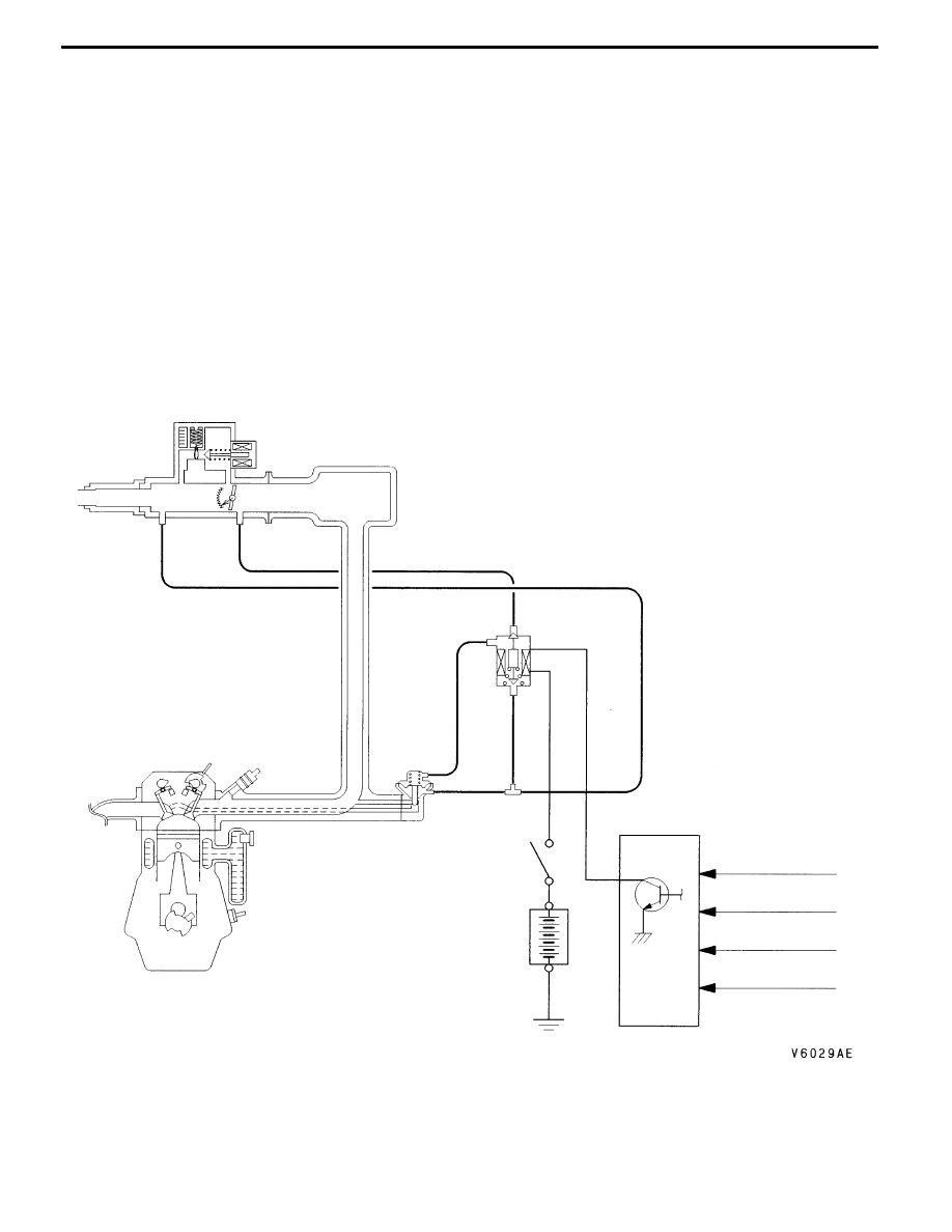
SYSTEM DIAGRAM

ON

Throttle body

EGR control

solenoid valve

Engine

control

relay

Battery

EGR valve

Crank angle sensor

Throttle position sensor

Engine-ECU

Engine coolant

temperature sensor

Air flow sensor

ENGINE AND EMISSION CONTROL -

Emission Control System

EGR control solenoid valve

Vacuum tank

Alternator

EGR valve

Throttle body

17-14

COMPONENT LOCATION

EXHAUST GAS RECIRCULATION (EGR)

CONTROL SYSTEM CHECK

1. Disconnect the vacuum hose (green stripe) from the EGR

control solenoid valve, and then connect a hand vacuum

pump via the three-way terminal.

2. When the engine is hot or cold, check the condition of

vacuum by racing the engine.
When engine is cold

(Engine coolant temperature: 20_C or less)

Throttle valve

Normal vacuum condition

Open quickly

No vacuum will generate
(the same as barometric pressure.)

When engine is hot

(Engine coolant temperature: 80_C or higher)

Throttle valve

Normal vacuum condition

Open quickly

It will momentarily rise over 13 kPa

3. Disconnect the three-way terminal.

4. Connect the hand vacuum pump to the vacuum hose

(green stripe).

5. Check whether the engine stalls or the idling is unstable

when a vacuum of 27 kPa or higher is applied during

idling.

Three-way

terminal

EGR control

solenoid valve

Vacuum

tank

Alternator

EGR control

solenoid valve

Vacuum

tank

Alternator

Green stripe

ENGINE AND EMISSION CONTROL -

Emission Control System

17-15

EGR VALVE CHECK

1. Remove the EGR valve and inspect for sticking, carbon

deposits, etc. If found, clean with a suitable solvent so

that the valve seats correctly.

2. Connect a hand vacuum pump to the EGR valve.

3. Apply 67 kPa of vacuum, and check that the vacuum

is maintained.

4. Apply a vacuum and check the passage of air by blowing

through one side of the EGR passage.

Vacuum

Passage of air

5.3 kPa or less

Air is not blown out

27 kPa or more

Air is blown out

5. Replace the gasket, and tighten to the specified torque.

Tightening torque: 20 ± 2 N·m

EGR PORT VACUUM CHECK

1. Disconnect the vacuum hose (White stripe) from the

throttle body EGR vacuum nipple and connect a hand

vacuum pump to the nipple.

2. Start the engine and check vacuum remains fairly constant

after racing the engine.
NOTE

If the vacuum fluctuates, the throttle body EGR port may

be clogged and need cleaning.

White stripe

Throttle body

Vacu-

um

Engine speed (r/min)

ENGINE AND EMISSION CONTROL -

Emission Control System

17-16

EGR CONTROL SOLENOID VALVE CHECK

NOTE

When disconnecting the vacuum hose, always make a mark

so that it can be reconnected at original position.

1. Disconnect the vacuum hose (yellow stripe, green stripe,

white stripe) from the solenoid valve.

2. Disconnect the harness connector.

3. Connect a hand vacuum pump to the nipple to which

the green-striped vacuum hose was connected.

4. Check airtightness by applying a vacuum with voltage

applied directly from the battery to the EGR control

solenoid valve and without applying voltage.

Battery voltage

B nipple condition

Normal condition

Not applied

Open

Vacuum maintained

Applied

Open

Vacuum leaks

Closed

Vacuum maintained

5. Measure the resistance between the terminals of the

solenoid valve.
Standard value: 29 - 35 Ω (at 20_C)

Battery

A

B

C


Content   ..  236  237  238  239   ..