Mitsubishi Lancer Evolution 7. Manual - part 224
INTAKE AND EXHAUST -
Exhaust Manifold
15-21
"
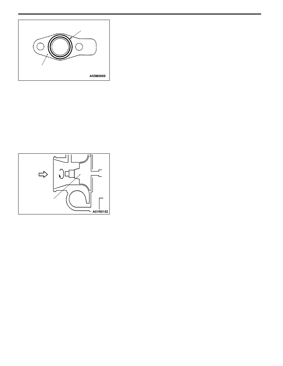
CA OIL RETURN PIPE GASKET INSTALLATION
Install the gasket so that its print part can face towards the
oil pan side.
INSPECTION
Check the following points; replace the part if a problem is
found.
1. EXHAUST MANIFOLD CHECK
(1) Check for damage or cracking of any part.
(2) Using a straight edge and a feeler gauge, check for
distortion of the cylinder head installation surface.
Standard value: 0.15 mm or less
Limit: 0.20 mm
2. TURBOCHARGER ASSEMBLY CHECK
(1) Visually check the turbine wheel and the compressor
wheel for cracking or other damage.
(2) Check whether the turbine wheel and the compressor
wheel can be easily turned by hand.
(3) Check for oil leakage from the turbocharger assembly.
(4) Check whether or not the waste gate valve remains open.
If any problem is found, replace the part after disassembly.
Gasket
Compressor wheel