Mitsubishi Lancer Evolution 7. Manual - part 218


  Index      Mitsubishi     Mitsubishi Lancer Evolution 7 - service repair manual


Search            


Content   ..  216  217  218  219   ..


Mitsubishi Lancer Evolution 7. Manual - part 218


ENGINE COOLING -

Water Hose and Water Pipe/Radiator

14-15

REMOVAL SERVICE POINT

A

ARADIATOR UPPER HOSE/RADIATOR LOWER

HOSE DISCONNECTION

After making mating marks on the hose and the hose clamp,

disconnect the hose.

INSTALLATION SERVICE POINTS
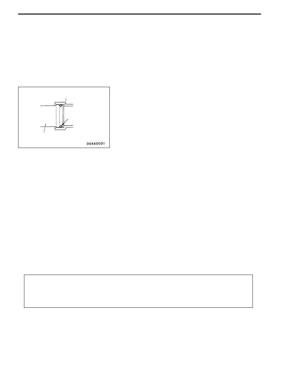
"

AO-RING INSTALLATION

Fit an O-ring into the groove of the water inlet pipe and

apply water to the circumference of the O-ring or the

inside of the mounting surface of the pipe for insertion.
CAUTION

Do not let the O-ring get contaminated with grease, such

as engine oil.

"

BWATER INLET PIPE INSTALLATION

After installing the water outlet fitting and the thermostat

case assembly, tighten the mounting bolt of the water

inlet pipe to the specified torque.
"

CRADIATOR LOWER HOSE/RADIATOR UPPER

HOSE CONNECTION

1. Insert each hose as far as the projection of the water

inlet pipe or water outlet fitting.

2. Align the mating marks on the radiator hose and hose

clamp, and then connect the radiator hose.

INSPECTION

WATER PIPE AND HOSE CHECK
Check the water pipe and hose for cracks, damage, clog

and replace them if necessary.

RADIATOR

REMOVAL AND INSTALLATION

Pre-remobal and Post-installation Operation
D

Engine Coolant Draining and Supplying (Refer to P.14-6.)

D

Under Cover Removal and Installation (Refer to GROUP 51 - Front Bumper.)

D

Air Cleaner Assembly Removal and Installation (Refer to GROUP 15.)

D

Air Hose E, Air Pipe C, Air hose D Removal and Installation (Refer to GROUP 15 - Intercooler.)

D

Battery and Battery Tray Removal and Installation

Water pump or

thermostat case

O-ring

Warter inlet pipe

ENGINE COOLING -

Radiator

14-16

1

2

3

4

5

6

7

12 ± 2 N·m

9

16

14

19

18

12

17

10

8

13

15

10

20

21

12 ± 2 N·m

5.0 ± 1.0 N·m

3.5 ± 0.4 N·m

4.5 ± 0.4 N·m

4.0 ± 0.4 N·m

13

11

12 ± 1 N·m

Radiator removal steps

1. Radiator drain plug

2. Radiator cap

3. Reserve tank hose

4. Reserve tank

5. Reserve tank cap

6. Reserve tank hose

7. Reserve tank bracket

A

A" "AA 8. Radiator upper hose

A

A" "AA 9. Radiator lower hose

10. Upper insulator

A

B"

11. Air Pipe B mounting bolt

12. Radiator assembly

13. Lower insulator

14. Radiator fan controller connector

15. Radiator fan controller, radiator fan

motor, fan and shroud assembly

Radiator fun controller and radiator

fun motor removal steps

A

B"

11. Air Pipe B mounting bolt

14. Radiator fan controller connector

16. Radiator fan motor connector

17. Radiator fan controller

18. Radiator fan motor fan and shroud

assembly

19. Fan

20. Radiator fan motor

21. Shroud

ENGINE COOLING -

Radiator

ENGINE COOLING -

Radiator

14-17

REMOVAL SERVICE POINTS

A

ARADIATOR UPPER HOSE/RADIATOR LOWER

HOSE REMOVAL

After making mating marks on the radiator hose and the hose

clamp,disconnect the radiator hose.

A

BAIR PIPE B MOUNTING BOLT REMOVAL

After removing the bolt, position air pipe B out of the way

so that the pipe does not interfere with the radiator assembly

or the radiator fan motor, the fan and shroud assembly.

INSTALLATION SERVICE POINT

"

ARADIATOR LOWER HOSE/RADIATOR UPPER

HOSE INSTALLATION

1. Insert each hose as far as the projection of the water

inlet pipe, water outlet fitting or radiator.

2. Align the mating marks on the radiator upper hose and

hose clamp, and then connect the radiator hose.

NOTES


Content   ..  216  217  218  219   ..