Mitsubishi Lancer Evolution 7. Manual - part 216


  Index      Mitsubishi     Mitsubishi Lancer Evolution 7 - service repair manual


Search            


Content   ..  214  215  216  217   ..


Mitsubishi Lancer Evolution 7. Manual - part 216


ENGINE COOLING -

On-vehicle Service

ENGINE COOLING -

On-vehicle Service

14-7

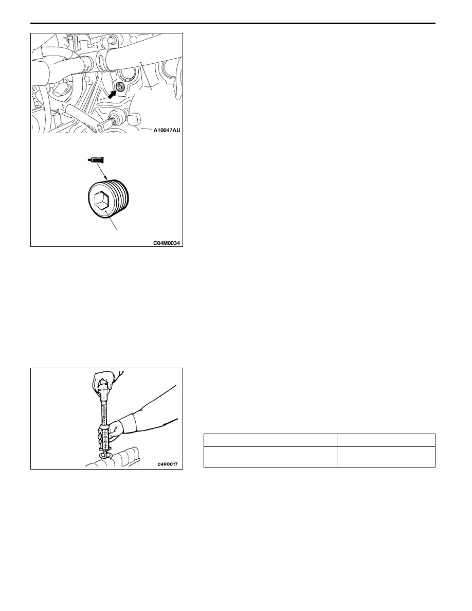
3. Remove the cylinder block drain plug from the cylinder

block to drain the engine coolant.

4. Remove the reserve tank to drain the engine coolant.

5. When the engine coolant has drained, pour in water from

the radiator cap to clean the engine coolant line.

6. Coat the thread of the cylinder block drain plug with the

specified sealant and tighten to the specified torque.
Specified sealant:

3M Nut Locking Part No. 4171 or equivalent

7. Securely tighten the radiator drain plug.

8. Install the under cover.

(Refer to GROUP 51 - Front Bumper.)

9. Install the reserve tank.

10. Slowly pour the engine coolant into the mouth of the

radiator until the radiator is full, and pour also into the

reserve tank up to the FULL line.
Recommended anti-freeze:

MITUBISHI GENUINE COOLANT or equivalent

Quantity: 6.0 L

Caution

Do not use alcohol or methanol anti-freeze or any

engine coolants mixed with alcohol or methanol

anti-freeze. The use of an improper anti-freeze can

cause the corrosion of the aluminium components.

11. Install the radiator cap securely.

12. Start the engine and warm the engine until the thermostat

opens. (Touch the radiator hose with your hand to check

that warm water is flowing.)

13. After the thermostat opens, race the engine several times,

and then stop the engine.

14. Cool down the engine, and then pour engine coolant into

the reserve tank until the level reaches the FULL line. If

the level is low, repeat the operation from step 11.

CONCENTRATION MEASUREMENT

Measure the temperature and specific gravity of the engine

coolant to check the antifreeze concentration.
Standard value: 30 - 60 % (allowable concentration range)
RECOMMENDED ANTI-FREEZE

Antifreeze

Allowable concentration

MITSUBISHI GENUINE COOLANT

or equivalent

30 - 60 %

Caution

If the concentration of the anti-freeze is below 30 %, the

anti-corrosion property will be adversely affected. In

addition, if the concentration is above 60 %, both the

anti-freezing and engine cooling properties will decrease,

affecting the engine adversely. For these reasons, be

sure to maintain the concentration level within the

specified range.

44 ± 5 N·m

Water inlet

pipe

ENGINE COOLING -

On-vehicle Service

14-8

RADIATOR FAN RELAY CONTINUITY CHECK

Battery voltage

Terminal No.

1

2

3

4

When current is not

supplied

When current is

supplied

RADIATOR FAN CONTROLLER CHECK

<Vehicles without A/C>

1. Remove the center under cover.

(Refer to GROUP 51 - Front Bumper.)

2. Insert the special tool at the back of the radiator fan

motor connector.

3. Connect the special tool to the circuit tester.

4. Disconnect the engine coolant temperature sensor

connector.

Air cleaner

Radiator fan

controller

MB991222

Circuit tester

Connector

rear view

Water outlet

fitting

Engine coolant

temperature

sensor

ENGINE COOLING -

On-vehicle Service

14-9

5. Connect the special tool (MB991658) to the harness side

of the engine coolant temperature sensor connector.

6. Connect the special tool [MB991791(APS)] to the special

tool (MB991658).

7. Start the engine and let it run at idle.

NOTE

Since the resistance value of the special tool (APS)

indicates a low engine coolant temperature, engine speed

increases.

8. When the lever of the special tool (APS) is turned to

the end, check that the engine speed decreases and

the radiator fan motor rotates.

9. When the lever of the special tool (APS) is turned to

the reverse direction, check that the voltage between

terminals of the radiator fan motor connector gradually

decreases from the battery voltage to 0 V.

10. If inoperable, replace the radiator fan controller.

(Refer to P.14-15.)

11. Install the center under cover.

(Refer to GROUP 51 - Front Bumper.)

12. Connect the engine coolant temperature sensor

connector.

<Vehicles with A/C>

1. Remove the center under cover.

(Refer to GROUP 51 - Front Bumper.)

2. Insert the special tool at the back of the radiator fan

motor connector.

3. Connect the special tool to the circuit tester.

4. Start the engine and run it at idle.

5. Turn the A/C switch to the ON position and hold the

engine coolant temperature at 80_C or lower.

6. When the voltage between the terminals of the radiator

fan motor connector, the following values of (1) - (3)

can be detected at random.

(1) 0 V

(2) 8.2  2.6 V

(3) Battery voltage  2.6 V

7. If inoperable, replace the radiator fan controller.

(Refer to P.14-15.)

8. Install the center under cover.

(Refer to GROUP 51 - Front Bumper.)

Engine coolant

temperature sensor

connector

(harness side)

MB991791(APS)

MB991658

MB991658

Lever

MB991791(APS)

Radiator fan

controller

MB991222

Circuit tester

Connector

rear view

ENGINE COOLING -

On-vehicle Service

14-10

RADIATOR FAN MOTOR CHECK

1. Remove the center under cover.

(Refer to GROUP 51 - Front Bumper.)

2. Disconnect the radiator fan motor connector.

3. Check that the motor rotates when energizing battery

voltage between the terminals of connectors of the radiator

fan motor side.Check that there is abonormal noise from

the radiator fan motor then.

4. If inoperable, replace the radiator fan motor.

(Refer to P.14-15.)

5. Install the center under cover.

(Refer to GROUP 51 - Front Bumper.)

Radiator fan motor


Content   ..  214  215  216  217   ..