Mitsubishi Lancer Evolution 7. Manual - part 215
ENGINE COOLING -
Special Tools/Troubleshooting
14-3
SPECIAL TOOLS
Tool
Number
Name
Use
A
B
C
D
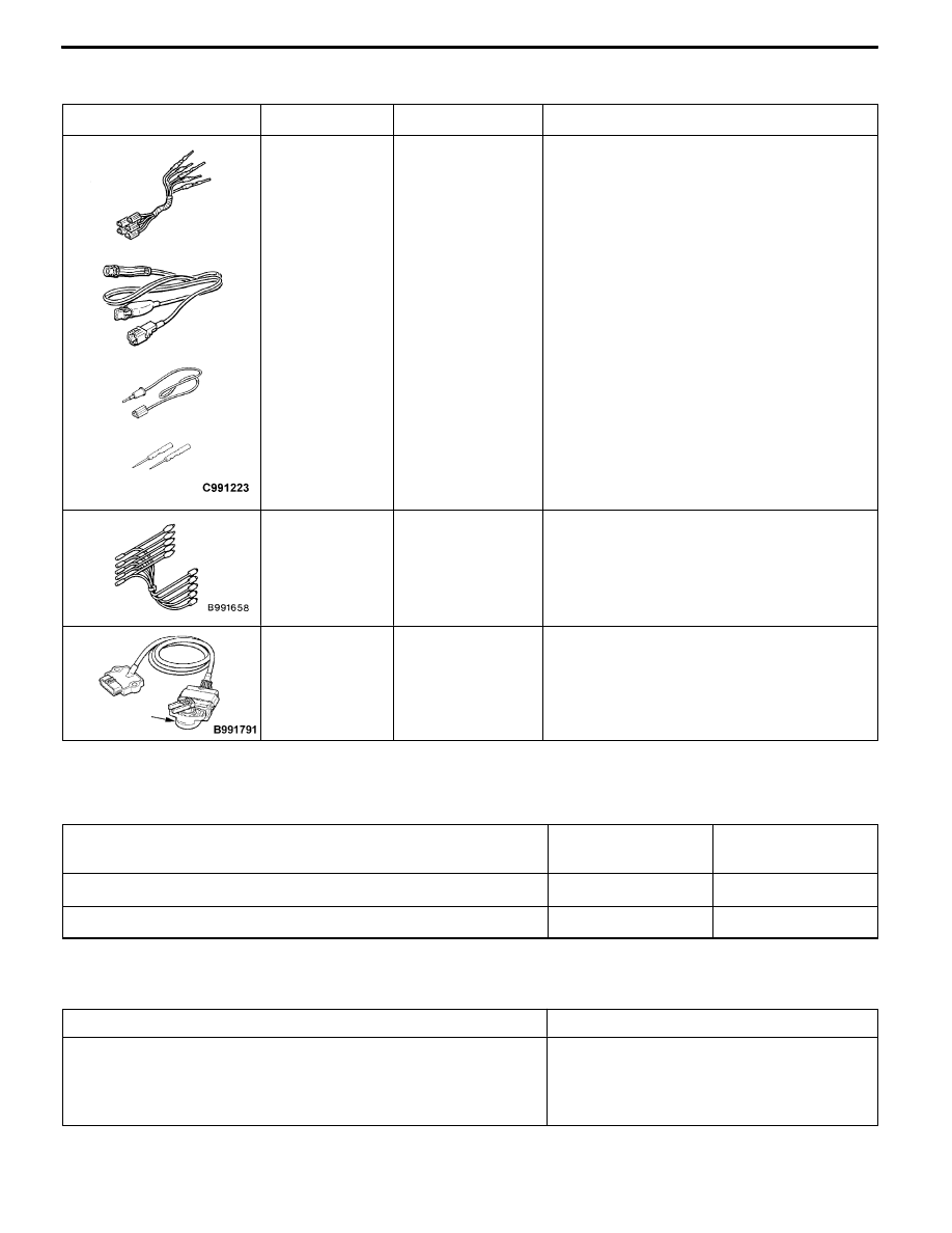
MB991223
A: MB991219
B: MB991220
C: MB991221
D: MB991222
Harness set
A: Test harness
B: LED harness
C: LED harness
adapter
D: Probe
D
Measurement of terminal voltage
D
Inspection of radiator fan controller
A: Connector pin contact pressure
inspection
B: Power circuit inspection
C: Power circuit inspection
D: Commercial tester connection
MB991658
Test harness
Inspection of radiator fan controller
APS
MB991791
Throttle cotroller
Inspection of radiator fan controller
[Use the accelerator pedal position sensor
disconnected from harness.]
TROUBLESHOOTING
INSPECTION CHART FOR TROUBLE SYMPTOMS
Trouble symptoms
Inspection procedure
No.
Reference page
Radiator fan does not operate.
1
14-3
Radiator fan does not change speed or stop.
2
14-5
INSPECTION PROCEDURE FOR TROUBLE SYMPTOMS
Inspection Procedure 1
Radiator fan does not operate.
Probable cause
Failure may occur on the power supply of the radiator fan controller and the
earth circuit.
Failure may also occur on the radiator fan controller and engine-ECU.
D
Malfunction of fusible link
D
Malfunction of radiator fan relay
D
Malfunction of radiator fan controller
D
Malfunction of radiator fan motor
D
Malfunction of engine-ECU
D
Malfunction of harness, connector