Mitsubishi Lancer Evolution 7. Manual - part 189
MPI -
Troubleshooting
13A-55
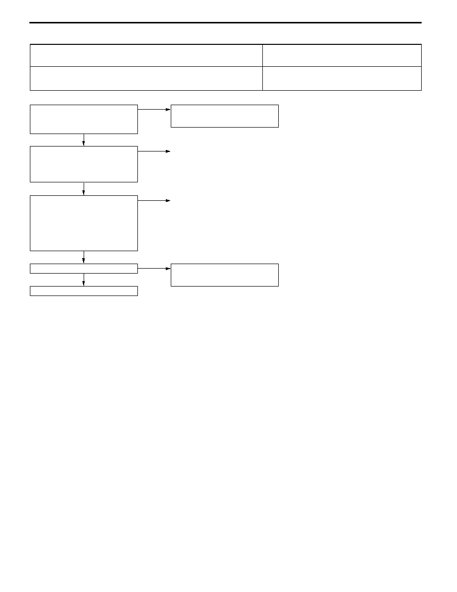
Inspection Procedure 2
Only communication between MUT-II and engine-ECU is
not possible.
Probable cause
Causes shown on right are suspected.
D
Ignition switch malfunction
D
Engine control relay malfunction
D
Engine-ECU malfunction
NG
Replace the engine-ECU.
OK
Check the trouble symptoms.
OK
Intermittent malfunction
(Refer to GROUP 00 - Points to Note
for Intermittent Malfunctions.)
OK
Check the harness between the
diagnosis connector and engine-ECU.
D
Check for disconnection,
short-circuit and damage of the
communication cable.
D
Check for disconnection,
short-circuit and damage of the
signal cable.
NG
Repair
OK
Check the following connectors:
C-26, C-130, C-118, C-108, C-28
<R.H. drive vehicles>, C-102 <L.H.
drive vehicles>, C-145 <Vehicles with
MMCS>
NG
Repair
Check the engine warning lamp.
D
Ignition switch: ON
OK: Engine warning lamp is
illuminated.
NG
Check the Inspection Procedure 22:
Engine-ECU power supply, engine
control relay, ignition switch-IG system.
NOTE
If the problem symptom does not disappear in the vehicle with MMCS after carrying out the above-mentioned
inspection procedure, there may be a malfunction in the multi-center display.