Mitsubishi Lancer Evolution 7. Manual - part 187


  Index      Mitsubishi     Mitsubishi Lancer Evolution 7 - service repair manual


Search            


Content   ..  185  186  187  188   ..


Mitsubishi Lancer Evolution 7. Manual - part 187


MPI -

Troubleshooting

13A-47

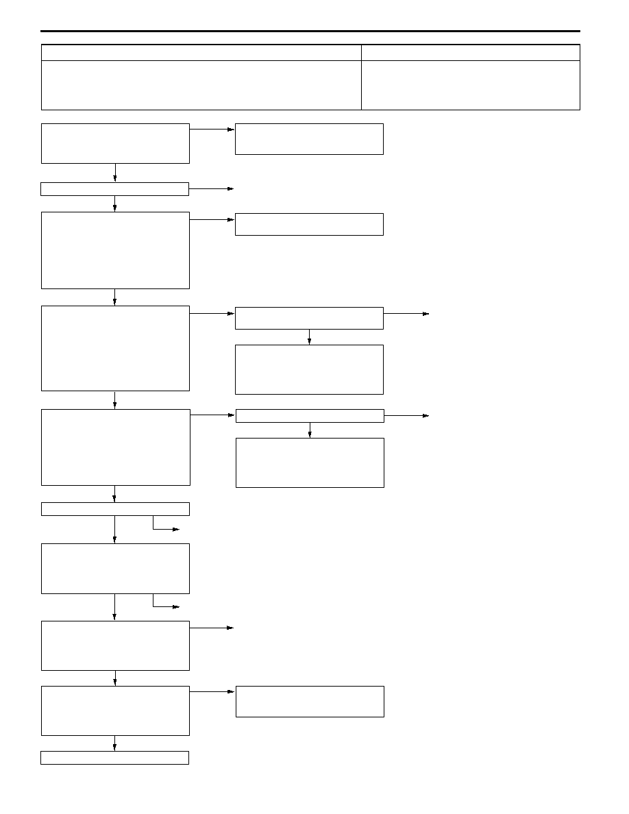
Code No. P1104 Waste gate solenoid valve system

Probable cause

Inspection Range
D

Battery voltage is more than 10 V.

Evaluation Conditions
D

Solenoid coil’s surge voltage (battery voltage +2 V) is not detected when the

waste gate solenoid valve turned from ON to OFF.

D

Waste gate solenoid valve malfunction

D

Engine-ECU malfunction

OK

NG

Replace the engine-ECU.

OK

Intermittent malfunction (Refer to

GROUP 00 - Points to Note for

Intermittent Malfunctions.)

MUT-II Actuator Test
D

No. 12: Waste gate solenoid

valve

OK: Operation sound is heard,

and there is vibration.

OK

NG

Repair

OK

NG

Intermittent malfunction (Refer to

GROUP 00 - Points to Note for

Intermittent Malfunctions.)

OK

Check the following connector: B-36

MUT-II Actuator Test
D

No. 12: Waste gate solenoid valve

OK: Operation sound is heard,

and there is vibration.

NG

Repair

NG

NG

Repair

OK

Check the harness between the

waste gate solenoid valve and

engine-ECU.
D

Check for disconnection and

short-circuit of the output cable.

Check the following connector: C-39

OK

Check the following connector: C-126

Measure at the C-126 engine-ECU

connector.
D

Disconnect the connector to

measure at the harness side.

D

Ignition switch: ON

D

Voltage between terminal No. 11

and earth

OK: System voltage

NG

Replace the waste gate solenoid

valve.

Measure at the B-36 waste gate

solenoid valve connector.
D

Disconnect the connector to

measure at the solenoid valve

side.

D

Resistance between terminal No.

1 and terminal No. 2

OK: 29 - 35 Ω (at 20_C)

OK

NG

Measure at the B-36 waste gate

solenoid valve connector.
D

Disconnect the connector to

measure at the harness side.

D

Ignition switch: ON

D

Voltage between terminal No. 1

and earth

OK: System voltage

OK

NG

Repair

OK

OK

Check and repair the harness between

the waste gate solenoid valve and

engine control relay.
D

Check for disconnection and

short-circuit of the power cable.

Check the following connector:

B-11X

NG

Repair

Check the harness between the

waste gate solenoid valve and

engine control relay.
D

Check for damage of the power

cable.

NG

Repair

OK

Check the harness between the

waste gate solenoid valve and

engine-ECU.
D

Check for damage of the output

cable.

MPI -

Troubleshooting

13A-48

Code No. P1105 Fuel pressure control solenoid valve

system

Probable cause

Inspection Range
D

Battery voltage is more than 10 V.

Evaluation Conditions
D

Solenoid coil’s surge voltage (battery voltage +2 V) is not detected when the

fuel pressure control solenoid valve turned from ON to OFF.

D

Fuel pressure control solenoid valve malfunction

D

Engine-ECU malfunction

OK

NG

Replace the engine-ECU.

OK

Intermittent malfunction (Refer to

GROUP 00 - Points to Note for

Intermittent Malfunctions.)

MUT-II Actuator Test
D

No. 09: Fuel pressure control

solenoid valve

OK: Operation sound is heard,

and there is vibration.

OK

NG

Repair

OK

NG

Intermittent malfunction (Refer to

GROUP 00 - Points to Note for

Intermittent Malfunctions.)

OK

Check the following connector: B-37

MUT-II Actuator Test
D

No. 08: Purge control solenoid

valve

OK: Operation sound is heard,

and there is vibration.

NG

Repair

NG

NG

Repair

OK

OK

Check and repair the harness

between the fuel pressure control

solenoid valve and engine-ECU.
D

Check for disconnection and

short-circuit of the output cable.

Check the following connector:

C-126

OK

Check the following connector: C-126

Measure at the C-126 engine-ECU

connector.
D

Disconnect the connector to

measure at the harness side.

D

Ignition switch: ON

D

Voltage between terminal No. 3

and earth

OK: System voltage

NG

Replace the fuel pressure control

solenoid valve.

Measure at the B-37 fuel pressure

control solenoid valve connector.
D

Disconnect the connector to

measure at the solenoid valve

side.

D

Resistance between terminal No.

1 and terminal No. 2

OK: 29 - 35 Ω (at 20_C)

OK

NG

Measure at the B-37 fuel pressure

control solenoid valve connector.
D

Disconnect the connector to

measure at the harness side.

D

Ignition switch: ON

D

Voltage between terminal No. 1

and earth

OK: System voltage

OK

NG

Repair

OK

OK

Check and repair the harness between

the fuel pressure control solenoid valve

and engine control relay.
D

Check for disconnection and

short-circuit of the power cable.

Check the following connector:

B-11X

NG

Repair

Check the harness between the fuel

pressure control solenoid valve and

engine control relay.
D

Check for damage of the power

cable.

NG

Repair

OK

Check the harness between the fuel

pressure control solenoid valve and

engine-ECU.
D

Check for damage of the output

cable.

MPI -

Troubleshooting

13A-49

Code No. P1500 Alternator FR terminal system

Probable cause

Inspection Range
D

Engine speed: More than 50 r/min

Evaluation Conditions
D

The input voltage from the alternator FR terminal is between 4.8 V and 5.2 V

or is the battery voltage for 20 seconds.

D

Open circuit in the alternator FR terminal circuit

D

Malfunction of engine-ECU

OK

Intermittent Malfunction

(Refer to GROUP 00 - Points to

Note for Intermittent Malfunction.)

OK

Check the trouble symptoms.

NG

Replace the engine-ECU.

OK

Intermittent Malfunction

(Refer to GROUP 00 - Points to

Note for Intermittent Malfunction.)

OK

Check the trouble symptoms.

NG

Replace the alternator.

NG

OK

Check the harness between the middle

connector and engine-ECU.
D

Check for damage of the output

wire.

Repair

NG

OK

Check the harness between the

alternator and middle connector.
D

Check for damage of the output

wire.

Repair

OK

Measure at the B-14 middle

connector.
D

Using the test harness

(MB991658), connect the

connector and measure at the

pickup harness.

D

Engine: Idling (After warm-up)

D

Radiator fan: OFF

D

Voltage between terminal No. 5

and earth.

OK: The voltage drops when

the headlamp is turned

from OFF to ON.

NG

Check the following connector:

B-22

NG

Repair

OK

Replace the alternator.

NG

OK

Check the harness between the

alternator and middle connector.
D

Check for short circuit of the

output wire.

Repair

OK

Measure at the B-14 middle

connector.
D

Using the test harness

(MB991658), connect the

connector and measure at the

pickup harness.

D

Ignition switch: ON

D

Voltage between terminal No.5

and earth.

OK: 5 - 6 V

NG

Check the following connector:

B-22

NG

Repair

OK

Intermittent Malfunction

(Refer to GROUP 00 - Points to

Note for Intermittent Malfunction.)

OK

Check the trouble symptoms.

NG

Replace the engine-ECU.

NG

OK

Check the harness between the

middle connector and engine-ECU.
D

Check for short circuit of the

output wire.

Repair

OK

Measure at the B-14 middle

connector.
D

Disconnect the connector to

measure at the female connector

side.

D

Ignition switch: ON

D

Voltage between terminal No.5

and earth.

OK: 4.9 - 5.1 V

NG

Check the following connector:

C-122

NG

Repair

Check the following connector:

B-14

NG

Repair

MPI -

Troubleshooting

13A-50

Code No. P1603 Battery backup line malfunction

Probable cause

Inspection Range
D

Ignition switch: ON

Evaluation Conditions
D

The backup RAM information set at the last time when the ignition switch

was turned to the OFF position is not memorized.

D

Battery backup line disconnection, short circuit or

connector contact defect

D

Engine-ECU malfunction

NG

Replace the engine-ECU

OK

Check the trouble symptoms.

OK

Intermittent Malfunction (Refer to

GROUP 00 - Points to Note for

Intermittent Malfunction.)

OK

Check the following connector:

C-115

NG

Repair

OK

Check and repair the harness

between battery and engine-ECU.
D

Check for disconnection and

short-circuit of the power cable.

NG

Check the following connector:

C-129, C-05, C-135

NG

Repair

NO

MUT-II Self-Diag code
D

Diagnosis codes No. P1603 is

output.

End

NO

Measure at the C-115 engine-ECU

connector.
D

Disconnect the connector to

measure at the harness side.

D

Voltage between terminal No.80

and earth.

OK: System voltage

YES

Turn the ignition switch to the

“LOCK”(OFF) position and then in 10

seconds turn the ignition switch to the

“ON” position

Is the battery terminal disconnected

before reading the diagnostic trouble

code?


Content   ..  185  186  187  188   ..