Mitsubishi Lancer Evolution 7. Manual - part 186


  Index      Mitsubishi     Mitsubishi Lancer Evolution 7 - service repair manual


Search            


Content   ..  184  185  186  187   ..


Mitsubishi Lancer Evolution 7. Manual - part 186


MPI -

Troubleshooting

13A-43

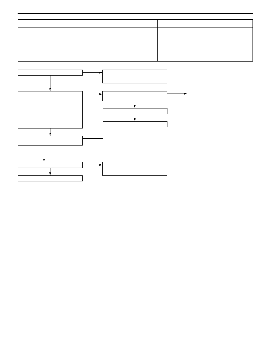
Code No. P0500 Vehicle speed sensor system

Probable cause

Inspection Range
D

Ignition switch: ON

D

After 2 seconds from setting ignition switch to ON position or completion of engine

starting

D

The engine speed is approximately 2,000 - 4,000 r/min or more.

D

The volumetric efficiency is 60 - 80%.

Evaluation Conditions
D

Vehicle speed signal does not change for 2 seconds. (Pulse signal is not input.)

D

Vehicle speed sensor malfunction

D

Vehicle speed sensor circuit disconnection,

short-circuit, or connector contact defect

D

Engine-ECU malfunction

NG

Replace the engine-ECU.

OK

Check the trouble symptoms.

OK

Intermittent malfunction

(Refer to GROUP 00 - Points to Note

for Intermittent Malfunctions.)

NG

Check the following connectors:

B-03, C-115

NG

Replace the engine-ECU.

OK

Check the trouble symptoms.

YES

Measure at the C-115 engine-ECU

connector.
D

Connect the connector.

D

Voltage between terminal No. 86

and earth

(Ignition switch: ON)

OK: When vehicle is pushed and

moved, repeatedly varies

between 0 and 5 V.

OK

Check the following connector:

C-115

NG

Repair

Is speedometer normal?

NO

Check the vehicle speed sensor.

(Refer to GROUP 54 - Combination

Meter.)

NG

Repair

MPI -

Troubleshooting

13A-44

Code No. P0505 Idle speed control system

Probable cause

Range of Check
D

Vehicle speed has reached 1.5 Km/h at least once.

D

Under the closed loop idle speed control.

Set Conditions
D

Actual idle speed has continued to be higher than the target idle speed by 300

r/min or more for 10 seconds.

Range fo Check
D

Vehicle speed has reached 1.5 km/h at least once.

D

During idle speed closed loop control.

D

The highest temperature at the last drive is 45_C or less.

D

Engine coolant temperature is approximately 80_C or more.

D

Battery voltage is 10 V or more.

D

Barometric pressure is 76 kPa or higher.

D

Intake air temperature is -10_C or more.

Set Conitions
D

Actual idle speed has been minimum 200 r/min higher than the target idle speed

for 10 seconds.

Range of Check
D

During idle speed closed loop control.

D

Engine coolant temperature is approximately 80_C or higher.

D

Battery voltage is 10 V or higher.

D

Power steering switch is off.

D

Volumetric efficiency is 40 % or lower.

D

Barometric pressure is 76 kPa or higher.

D

Intake air temperature is -10_C or more.

Set Conitions
D

Actual idle speed has been minimum 100 r/min higher than the target idle speed

for 10 seconds.

D

Malfunction of idle speed control servo

D

Open or short circuit in the idle speed control servo

circuit or loose connector contact

D

Malfunction of engine-ECU

MPI -

Troubleshooting

13A-45

OK

NG

OK

NG

Check and repair the harness

between the idle speed control servo

and engine control relay.
D

Check for disconnection and

short-circuit of the power cable.

OK

Measure at the B-115 idle speed

control servo connector.
D

Disconnect the connector to

measure at the harness side.

D

Ignition switch: ON

D

Voltage between terminal No. 2

and earth

D

Voltage between terminal No. 5

and earth

OK: System voltage

OK

Check the following connector:

B-11X

NG

NG

OK

Measure at the B-115 idle speed

control servo connector.
D

Disconnect the connector to

measure at the idle speed control

servo side.

D

Resistance between terminal No.

1 and terminal No. 2

D

Resistance between terminal No.

2 and terminal No. 3

D

Resistance between terminal No.

4 and terminal No. 5

D

Resistance between terminal No.

5 and terminal No. 6

OK: 28 - 33 Ω

Replace the idle speed control servo.

Check the following connector:

B-115

NG

Repair

NG

Check the harness between the idle speed control servo and

engine-ECU.
D

Check for damage of the output cable.

OK

Repair

NG

Repair

OK

OK

Repair

NG

Repair

OK

OK

Check the harness between the idle

speed control servo and engine-ECU.
D

Check for disconnection and

short-circuit of the output cable.

NG

Repair

Check the following connector:

C-126

NG

Replace the engine-ECU.

OK

Intermittent malfunction (Refer to

GROUP 00 - Points to Note for

Intermittent Malfunctions.)

Check the trouble symptoms.

Measure at the C-126 engine-ECU

connector.
D

Measure the engine-ECU terminal

voltage.

D

Voltage between terminal No. 4

and earth

D

Voltage between terminal No. 5

and earth

D

Voltage between terminal No. 17

and earth

D

Voltage between terminal No. 18

and earth

OK: After the warmed engine

completes starting, the volt-

age repeatedly fluctuates

as shown below.

<When using circuit tester>

System voltage ↔ 0 - 6 V

OK

Check the following connector:

C-126

NG

Repair

Check the harness between the idle sped control servo and

engine control relay.
D

Check for damage of the power cable.

NG

Replace the engine-ECU.

OK

Intermittent malfunction (Refer to

GROUP 00 - Points to Note for

Intermittent Malfunctions.)

Check the trouble symptoms.

MPI -

Troubleshooting

13A-46

Code No. P0551 Power steering fluid pressure switch

system

Probable cause

Range of Check
D

Intake air temperature is -10_C or higher.

D

Barometric pressure is 76 kPa or more.

D

Engine coolant temperature is 30_C or more.

D

Repeat the *1 drive and *2 stop ten times or more.

*1: Engine speed is 2500 r/min or higher, volumetric efficiency is 55 % or higher and

vehicle speed is 5 km/h or higher for 4 seconds or more.

*2: Vehicle speed is 1.5 km/h or lower.

Set Conditions
D

Power steering fluid pressure switch remains on.

D

Power steering fliud pressure switch failed

D

Open or short circuit in the power steering fluid

pressure switch circuit or loose conector contact

D

Mulfunction of engine-ECU

NG

OK

OK

NG

Check the following connectors:

C-122, C-136

NG

OK

NG

OK

Check the harness between the

power steering fluid pressure switch

and engine-ECU.
D

Check for short-circuit of the

output cable.

Repair

Repair

OK

Intermittent malfunction (Refer to GROUP 00 - Points to Note

for Intermittent Malfunctions.)

NG

OK

Measure at the A-48 power steering

fluid pressure switch connector.
D

Disconnect the connector to

measure at the harness side.

D

Ignition switch: ON

D

Voltage between terminal No. 1

and earth

OK: System voltage

NG

Measure at the C-122 engine-ECU

connector.
D

Measure the engine-ECU terminal

voltage.

D

Ignition switch: ON

D

Voltage between terminal No. 37

and earth

OK: System voltage

OK

NG

Replace the engine-ECU.

MUT-II Data list
D

No. 27: Power steering fluid pressure switch (Refer to

P.13A-103.)

OK

Check the following connector: A-48

NG

Repair

NG

Repair

OK

Check the following connector:

C-126, C-136

Check and repair the harness

between the power steering fluid

pressure switch and engine-ECU.
D

Check for disconnection of the

output cable.

Replace the engine-ECU.

OK

NG

MUT-II Data list
D

No. 27: Power steering fluid

pressure switch (Refer to

P.13A-103.)

Intermittent malfunction (Refer to

GROUP 00 - Points to Note for

Intermittent Malfunctions.)

Measure at the C-122 engine-ECU connector.
D

Measure the engine-ECU terminal voltage.

D

Engine: Idling

D

Voltage between terminal No. 37 and earth

D

Steering wheel: Stationary state

OK: System voltage

D

Steering wheel: Steered state

OK: 1 V or less

OK

Replace the power steering fluid

pressure switch.

Repair

Check the following connector:

C-122

NG

Repair

Check the following connector: C-122

Check the harness between the

power steering fluid pressure switch

and engine-ECU.
D

Check for damage of the output

cable.

OK

Repair

NG


Content   ..  184  185  186  187   ..