Mitsubishi Lancer Evolution 7. Manual - part 184


  Index      Mitsubishi     Mitsubishi Lancer Evolution 7 - service repair manual


Search            


Content   ..  182  183  184  185   ..


Mitsubishi Lancer Evolution 7. Manual - part 184


MPI -

Troubleshooting

13A-35

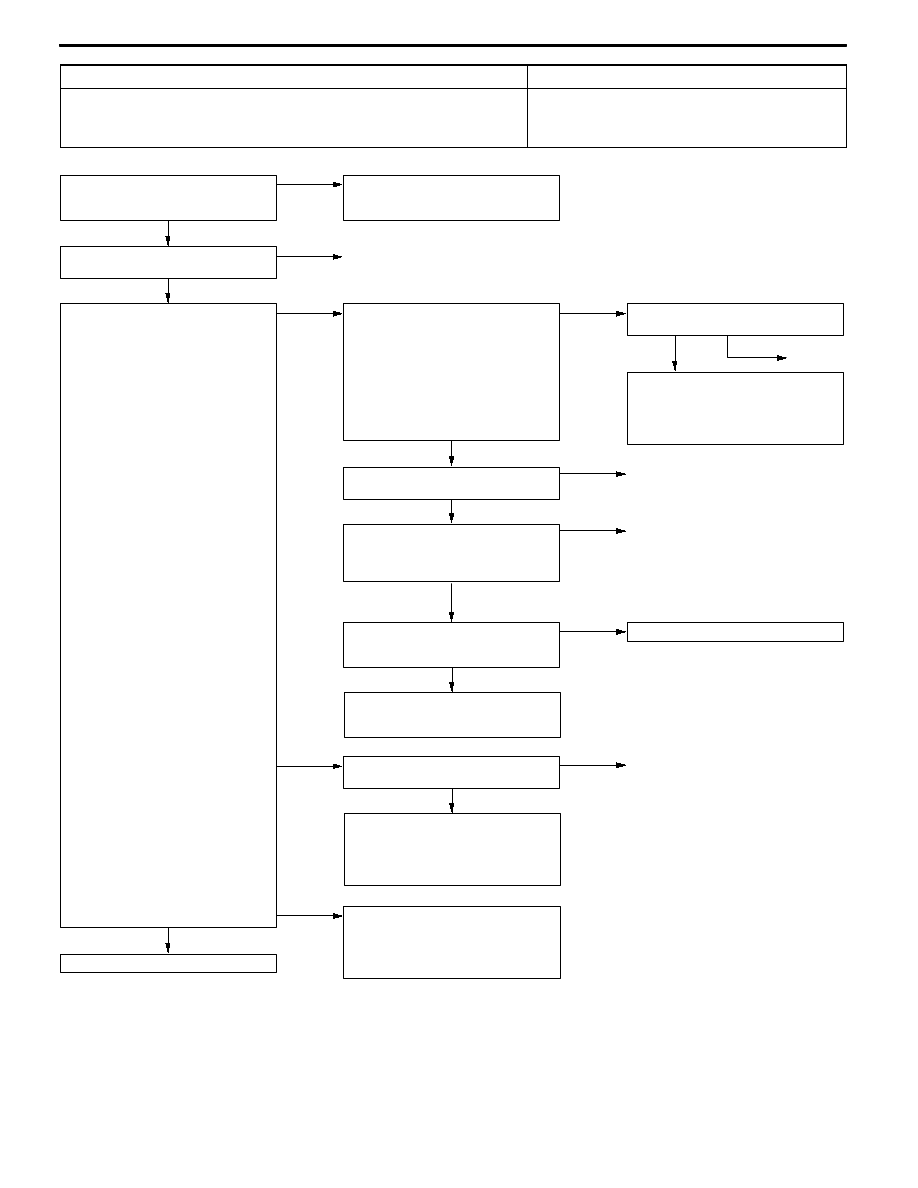
Code No. P0335 Crank angle sensor system

Probable cause

Inspection Range
D

Engine: During cranking

Evaluation Conditions
D

The sensor output voltage does not change for 2 seconds (no pulse signal output)

D

Malfunction of crank angle sensor

D

Open or short circuit in the crank angle sensor circuit

or loose connector contact

D

Malfunction of engine-ECU

OK

To the next page

(3) NG

Check the harness between the crank

angle sensor and body earth, and

repair if necessary.
D

Check for open circuit and damage

of the earth wire.

OK

Check the harness between the crank

angle sensor and engine control relay,

repair if necessary.
D

Check for open circuit and short

circuit of the power cable.

(2) NG

Check the following connector:

B-11X

NG

Repair

OK

Intermittent Malfunction

(Refer to GROUP 00 - Points to Note

for Intermittent Malfunction.)

OK

MUT-II Data list
D

No. 22 Crank angle sensor

(Refer to P.13A-103.)

NG

Replace the engine-ECU.

NG

OK

Check the harness between the crank

angle sensor and engine-ECU.
D

Check for short circuit of the output

wire.

Repair

OK

Check the harness between the crank

angle sensor and engine-ECU, and

repair if necessary.
D

Check for open circuit of the output

wire.

NG

Repair

NG

NG

Check the following connector:

C-115

Repair

OK

Measure at the B-121 crank angle

sensor connector.
D

Disconnect the connector to

measure at the harness side

(1) Voltage between terminal No. 2 and

earth.

(Ignition switch: ON)

OK: 4.9 - 5.1 V

(2) Voltage between terminal No. 3 and

earth.

(Ignition switch: ON)

OK: System voltage

(3) Resistance between terminal No. 1

and earth.

OK: Less than 2 Ω

(1) NG

Measure at the C-115 engine-ECU

connector.
D

Measure the engine-ECU terminal

voltage.

D

Disconnect the crank angle sensor

connector B-121.

D

Ignition switch: ON

D

Voltage between terminal No. 89

and earth.

OK: 4.9 - 5.1 V

OK

Check the following connector:

C-115

NG

Check the following connector:

B-121

NG

Repair

MUT-II Data list
D

No. 22 Crank angle sensor

(Refer to P.13A-103.)

OK

Intermittent Malfunction

(Refer to GROUP 00 - Points to Note

for Intermittent Malfunction.)

MPI -

Troubleshooting

13A-36

OK

Intermittent Malfunction

(Refer to GROUP 00 - Points to Note

for Intermittent Malfunction.)

OK

MUT-II Data list
D

No. 22 Crank angle sensor

(Refer to P.13A-103.)

NG

Replace the engine-ECU.

OK

Intermittent Malfunction

(Refer to GROUP 00 - Points to Note

for Intermittent Malfunction.)

OK

Check the trouble symptos.

NG

Replace the crank angle sensor.

OK

Check for crank angle sensor vane.

NG

Replace the crank angle sensor vane.

NG

OK

Check the harness between the crank

angle sensor and body earth.
D

Check for damage of the earth

wire.

Repair

NG

OK

Check the harness between the crank

angle sensor and engine-ECU.
D

Check for damage of the output

wire.

Reapir

NG

OK

Check the following connector:

C-115

Repair

NG

OK

Check the harness between the crank

angle sensor and engine control relay.
D

Check for damage of the power

cable.

Repair

OK

Measure the output waveform at the

B-121 crank angle sensor connector

(using an analyzer).
D

Using the test harness

(MD998478), connect the

connector, and measure at the

pickup harness.

D

Engine: Idle

D

Voltage between terminal No.2 and

earth.

OK: The waveform shown on

P.13A-117 (Inspection Proce-

dure Using Analyzer), should

be output,and the maximum

value should be more than

4.8 V, and the minimum value

less than 0.6 V. No noise

should be detected in the

output waveform.

NG

Check the following connector:

B-11X

NG

Repair

From the previous page

MPI -

Troubleshooting

13A-37

Code No. P0340 Camshaft position sensor system

Probable cause

Inspection Range
D

Ignition switch: ON

D

The engine speed is approximately 50 r/min or more.

Evaluation Conditions
D

The sensor output voltage does not change for 2 seconds (no pulse signal output)

D

Malfunction of camshaft position sensor

D

Open or short circuit in the camshaft position sensor

or loose connector contact

D

Malfunction of engine-ECU

OK

To the next page

(3) NG

Check the harness between the

camshaft position sensor connector

and body earth, and repair if

necessary.
D

Check for open circuit and damage

of the earth wire.

OK

Intermittent Malfunction

(Refer to GROUP 00 - Points to Note

for Intermittent Malfunction.)

OK

Check the trouble symptoms.

NG

Replace the engine-ECU.

OK

Check the harness between the

camshaft position sensor and

engine-ECU.
D

Check for short circuit of the output

wire.

NG

Repair

NG

Check the following connector:

C-115

NG

Repair

OK

Check the harness between the

camshaft position sensor and

engine-ECU and repair if necessary.
D

Check for open circuit of the output

wire.

NG

Repair

(2) NG

Measure at the C-115 engine-ECU

connector.
D

Measure the engine-ECU terminal

voltage.

D

Disconnect the camshaft position

sensor connector B-116.

D

Ignition switch: ON

D

Voltage between terminal No. 88

and earth.

OK: 4.9 - 5.1 V

OK

Check the following connector:

C-115

OK

Check the harness between the

camshaft position sensor connector

and engine control relay, and repair if

necessary.
D

Check for open circuit and short

circuit of the power cable.

OK

Measure at the B-116 camshaft

position sensor connector.
D

Disconnect the connector to

measure at the harness side

(1) Voltage between terminal No. 3 and

earth.

(Ignition switch: ON)

OK: System voltage

(2) Voltage between terminal No. 2 and

earth.

(Ignition switch: ON)

OK: 4.9 - 5.1 V

(3) Resistance between terminal No. 1

and earth.

OK: Less than 2 Ω

(1) NG

Check the following connector:

B-11X

NG

Repair

Check the following connector:

B-116

NG

Repair

MPI -

Troubleshooting

13A-38

OK

Intermittent Malfunction

(Refer to GROUP 00 - Points to Note

for Intermittent Malfunction.)

OK

Check the trouble symptoms.

NG

Replace the engine-ECU.

OK

Intermittent Malfunction

(Refer to GROUP 00 - Points to Note

for Intermittent Malfunction.)

OK

Check the trouble symptos.

NG

Replace the camshaft position sensor.

OK

Check the camshaft position sensing

cylinder.

NG

Replace the camshaft position sensing

cylinder.

NG

OK

Check the harness between the

camshaft position sensor and body

earth.
D

Check for damage of the earth

wire.

Repair

NG

OK

Check the harness between the

camshaft position sensor and

engine-ECU.
D

Check for damage of the output

wire.

Reapir

NG

OK

Check the following connector:

C-115

Repair

NG

OK

Check the harness between the

camshaft position sensor connector

and engine control relay.
D

Check for damage of the power

cable.

Repair

OK

Measure the output waveform at the

B-116 camshaft position sensor

connector (using an analyzer).
D

Using the test harness

(MB991709), connect the

connector, and measure at the

pickup harness.

D

Engine: Idle

D

Voltage between terminal No. 2

and earth.

OK: The waveform shown on

P.13A-117 (Inspection Proce-

dure Using Analyzer), should

be output,and the maximum

value should be more than

4.8 V, and the minimum value

less than 0.6 V. No noise

should be detected in the

output waveform.

NG

Check the following connector:

B-11X

NG

Repair

From the previous page


Content   ..  182  183  184  185   ..