Mitsubishi Lancer Evolution 7. Manual - part 182


  Index      Mitsubishi     Mitsubishi Lancer Evolution 7 - service repair manual


Search            


Content   ..  180  181  182  183   ..


Mitsubishi Lancer Evolution 7. Manual - part 182


MPI -

Troubleshooting

13A-27

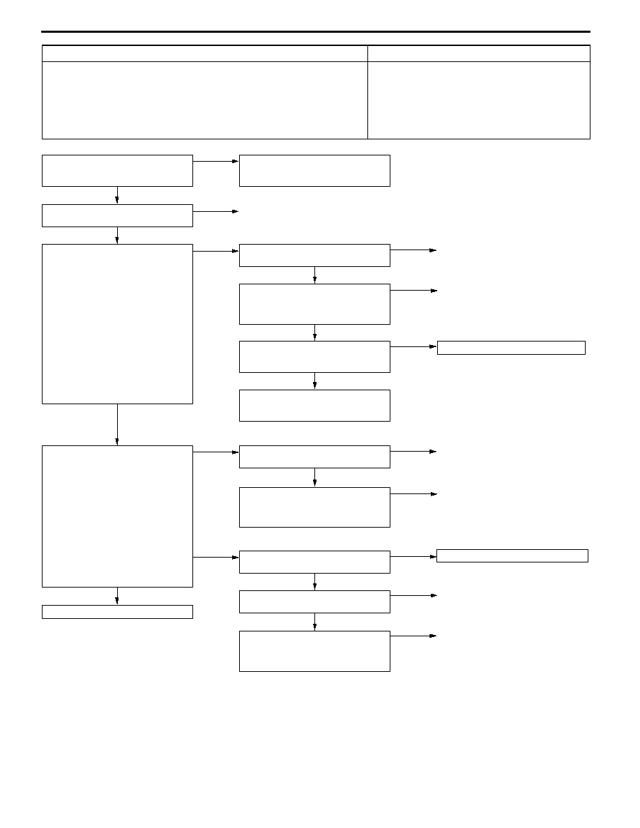
Code No. P0136 Oxygen sensor (rear) system

Probable cause

Inspection Range
D

More than 3 minutes passed after completion of start of engine

D

The engine coolant temperature is approximately more than 80_C.

D

The engine speed is more than 1,200 r/min.

D

The volumetric efficiency is 25% or more.

Evaluation Conditions
D

When 5 V is applied to the oxygen sensor (rear), the output voltage is more

than 4.5 V.

D

Oxygen sensor (rear) malfunction

D

Oxygen sensor (rear) circuit disconnection,

short-circuit, or connector contact defect.

D

Engine-ECU malfunction

OK

To the next page

OK

Check the harness between the

oxygen sensor (rear) and engine-ECU.
D

Check for damage of the output

wire.

NG

Repair

NG

OK

Check the following connector:

C-115

Repair

(2) NG

Check the oxygen sensor (rear).

(Refer to P.13A-135.)

NG

Replace the oxygen sensor (rear).

OK

Check the harness between the

oxygen sensor (rear) and engine-ECU.
D

Check for damage of the earth

wire.

NG

Repair

OK

Measure at the D-22 oxygen sensor

(rear) connector.
D

Using the test harness

(MB998464), connect the

connector, and measure at the

pickup harness.

D

Engine: After warm-up

(1) Voltage between terminal No. 2

and earth

OK: Less than 0.5 V

(2) Voltage between terminal No. 1

and the earth

D

During rapid racing

OK: 0 and 600 - 1,000 mV

alternate.

(1) NG

Check the following connector:

C-115

NG

Repair

OK

Intermittent malfunction

(Refer to GROUP 00 - Points to Note

for Intermittent Malfunctions.)

OK

MUT-II Data list
D

No. 59 Oxygen sensor (rear)

(Refer to P.13A-105.)

NG

Replace engine-ECU.

OK

Check the harness between the

oxygen sensor (rear) and engine-ECU.
D

Check for disconnection and

damage of the earth wire.

NG

Repair

OK

Measure at the D-22 oxygen sensor

(rear) connector.
D

Disconnect connector to measure

at the harness side

D

Resistance between terminal No.

2 and earth.

OK: Less than 2 Ω

NG

Check the following connector:

C-115

NG

Repair

NG

Check the following connector:

D-22

NG

Repair

MUT-II Data list
D

No. 59 Oxygen sensor (rear)

(Refer to P.13A-105.)

OK

Intermittent malfunction

(Refer to GROUP 00 - Points to Note

for Intermittent Malfunctions.)

MPI -

Troubleshooting

13A-28

OK

Intermittent malfunction

(Refer to GROUP 00 - Points to Note

for Intermittent Malfunctions.)

OK

MUT-II Data list
D

No. 59 Oxygen sensor (rear)

(Refer to P.13A-105.)

NG

Replace the engine-ECU.

OK

Check the following connector:

C-115

NG

Repair

OK

Check and repair the harness between

the oxygen sensor (rear) and

engine-ECU.
D

Check for disconnection of the

output wire.

OK

Test at the C-115 engine-ECU

connector.
D

Measure the engine-ECU terminal

voltage.

D

Engine: After warm-up

D

Voltage between terminal No. 75

and earth.

D

During rapid racing

OK: 0 and 600 - 1,000 mV

alternate.

NG

Check the following connector:

C-115

NG

Repair

From the previous page

MPI -

Troubleshooting

13A-29

Code No. P0141 Oxygen sensor heater (rear) system

Probable cause

Inspection Range
D

The engine coolant water temperature is approximately more than 20_C.

D

The oxygen sensor heater (rear) is ON.

D

The engine speed is more than 50 r/min.

D

A/C relay: OFF, radiator fan: OFF

D

The battery voltage is 11 - 16 V.

Evaluation Conditions
D

The oxygen sensor heater (rear) current is less than 0.2 A or more than 3.5

A for 4 seconds.

D

Oxygen sensor heater (rear) malfunction

D

Oxygen sensor heater (rear) circuit disconnection,

short-circuit, or connector contact defect

D

Engine-ECU malfunction

OK

Intermittent malfunction

(Refer to GROUP 00 - Points to Note

for Intermittent Malfunctions.)

OK

Check the trouble symptom.

NG

Replace the engine-ECU.

OK

Check the harness between the

oxygen sensor (rear) and engine-ECU.
D

Check for damage of the earth

wire.

NG

Repair

OK

Check the harness between the

oxygen sensor (rear) and engine

control relay.
D

Check for damage of the power

cable.

NG

Repair

OK

Check the following connector:

B-11X, C-108

NG

Repair

OK

Replace the engine-ECU.

NG

OK

Check the harness between the

oxygen sensor (rear) and engine-ECU.
D

Check for disconnection and

short-circuit of the earth wire.

Repair

OK

Measure at the C-118 engine-ECU

connector.
D

Measure the engine-ECU terminal

voltage.

D

Ignition switch: ON

D

Voltage between terminal No. 54

and earth.

OK: System voltage

NG

Check the following connector:

C-118

NG

Repair

OK

Check and repair the harness between

the oxygen sensor (rear) and engine

control relay.
D

Check the power cable for

disconnection and short-circuit.

OK

Measure at the D-22 oxygen sensor

(rear) connector.
D

Disconnect the connector, and

measure at the harness.

D

Ignition switch: ON

D

Voltage between terminal No. 3

and earth

OK: System voltage

NG

Check the following connector:

B-11X

NG

Repair

OK

Measure at the D-22 oxygen sensor

(rear) connector.
D

Disconnect the connector, and

measure at the sensor.

D

Resistance between terminal No.

3 and terminal No. 4.

OK: 11 - 18 Ω

NG

Replace the oxygen sensor (rear).

Check the following connector:

D-22

NG

Repair

MPI -

Troubleshooting

13A-30

Code No. P0201 No. 1 injector system

Probable cause

Inspection Range
D

The engine speed is 50 - 1,000 r/min.

D

The throttle position sensor output voltage is 1.15 V or less.

D

MUT-II forced drive (actuator test) is not being carried out.

Evaluation Conditions
D

Surge voltage at injector coil is not detected for 2 seconds.

D

No. 1 injector malfunction

D

No. 1 injector circuit disconnection, short-circuit, or

connector contact defect

D

Engine-ECU malfunction

OK

Intermittent malfunction

(Refer to GROUP 00 - Points to Note

for Intermittent Malfunctions.)

OK

Measure the signal waveform at the

C-126 engine-ECU connector (using

an analyzer).
D

Engine: Idling

D

Voltage between terminal No. 1 and

earth

OK: The waveform shown on

P.13A-119 (Inspection Proce-

dure Using Analyzer) should

be output.

NG

Replace the engine-ECU.

OK

Check the harness between the No. 1

injector and engine-ECU.
D

Check for disconnection,

short-circuit and damage of the

output cable.

NG

Repair

OK

Check the following connector:

C-126

NG

Repair

OK

Check the harness between the resis-

tor (for injector) and engine control

relay.
D

Check for damage of the power

cable.

NG

Repair

OK

Check the harness between the No. 1

injector and resistor (for injector).
D

Check for damage of the power

cable.

NG

Repair

OK

Check and repair the harness between

the resistor (for injector) and engine

control relay.
D

Check for disconnection and

short-circuit of the power cable.

NG

OK

Check the harness between the No. 1

injector and resistor (for injector).
D

Check for disconnection and

short-circuit of the power cable.

Repair

OK

Check the resistor. (Refer to

P.13A-138.)

OK

Measure at the B-27 No. 1 injector

connector.
D

Disconnect the connector to

measure at the harness side.

D

Ignition switch: ON

D

Voltage between terminal No. 1 and

earth

OK: System voltage

NG

Check the following connectors:

B-11X, B-138, C-108

NG

Repair

OK

Measure at the B-27 No. 1 injector

connector.
D

Disconnect the connector to

measure at the injector side.

D

Resistance between terminal No. 1

and terminal No. 2

OK: 2 - 3 Ω

NG

Replace the No. 1 injector.

NG

Check the following connector:

B-27

NG

Repair

MUT-II Actuator test
D

No. 01: No. 1 injector

OK: The idling state changes.

OK

Intermittent malfunction

(Refer to GROUP 00 - Points to Note

for Intermittent Malfunctions.)


Content   ..  180  181  182  183   ..