Mitsubishi Lancer Evolution 7. Manual - part 172
ENGINE OVERHAUL -
Crankshaft and Cylinder Block
11B-65
INSTALLATION SERVICE POINTS
"
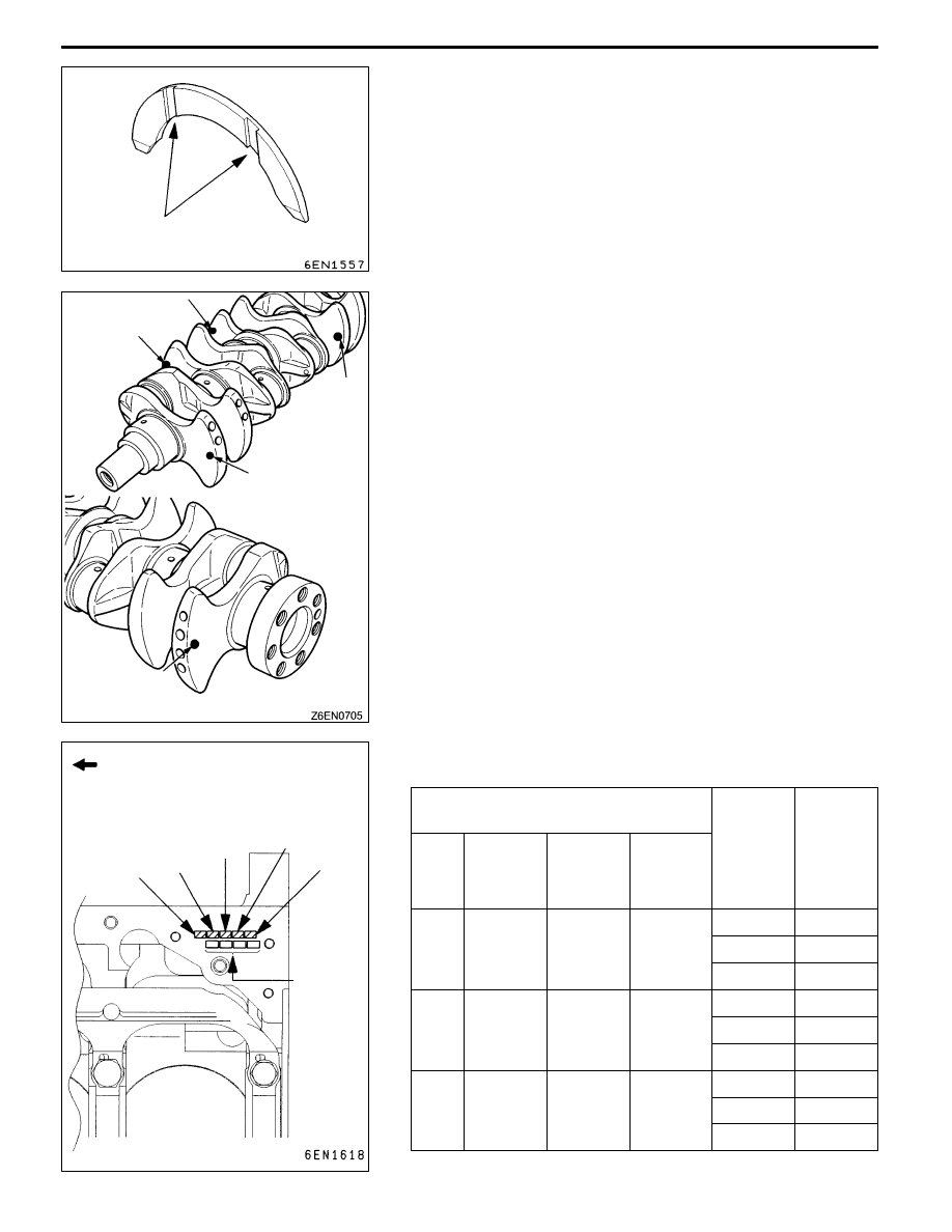
AA THRUST BEARING INSTALLATION
1. Install the thrust bearing onto the cylinder block side of
the No. 3 bearing section. The bearing can be installed
easily by applying engine oil.
2. Install the thrust bearing so that the side with the groove
faces the crankshaft weight side.
"
BA CRANKSHAFT BEARING INSTALLATION
1. Measure the diameter of the crankshaft journal, and
confirm the class shown below. When using a spare part,
each identification colour is painted at the position shown
in the illustration.
2. The cylinder block bearing section bore identification mark
is stamped at the position shown in the illustration.
Crankshaft journal
Cylinder
block
bearing
Spare
bearing
identifica
Class Product
identifica-
tion colour
Spare part
identifica-
tion colour
Journal
diameter
mm
bearing
section
bore iden-
tification
mark
identifica-
tion mark
1
None
Yellow
56.994 -
57 000
0
0
57.000
1
1
2
2
2
None
None
56.988 -
56 994
0
1
56.994
1
2
2
3
3
None
White
56.982 -
56 988
0
2
56.988
1
3
2
4
Groove
No. 2
No. 1
No. 4
No. 5
No. 3
Timing belt side
Cylinder block bearing section
bore identification mark
No. 1 No. 2
No. 3
No. 4
No. 5
Cylinder
bore size
mark