Mitsubishi Lancer Evolution 7. Manual - part 170
ENGINE OVERHAUL -
Piston and Connecting Rod
11B-57
REMOVAL SERVICE POINTS
A
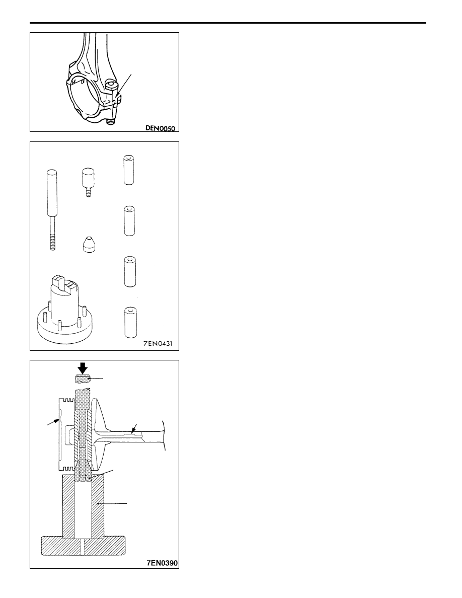
A" CONNECTING ROD CAP REMOVAL
Note the cylinder No. on the side of the connecting rod’s
large end for identification during reassembly.
A
B" PISTON PIN REMOVAL
The special tool’s piston pin setting tool (MD998780) is
configured of the parts shown in the left illustration.
1. Insert the special tool’s push rod in from the front mark
(arrow) side of the piston’s front face, and install guide
C.
2. Set the piston and connecting rod assembly onto the
special tool’s piston pin setting base so that the front
mark faces upward.
3. Push out the piston pin using a press.
NOTE
After removing the piston pin, group the piston, piston
pin and connecting rod for each cylinder No.
Cylinder No.
Push rod
Guide B
Guide A: 17.9 mm
Guide A: 18.9 mm
Guide A: 20.9 mm
Guide A: 21.9 mm
Base
Guide C
Push rod
Front mark
Guide C
Base
Front
mark