Mitsubishi Lancer Evolution 7. Manual - part 164
ENGINE OVERHAUL -
Water Pump and Water Hose
11B-33
INSTALLATION SERVICE POINTS
"
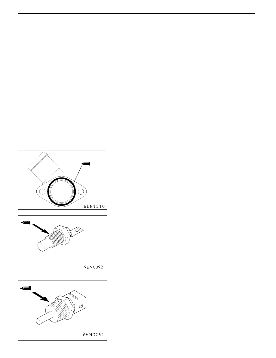
AA O-RING/WATER INLET PIPE INSTALLATION
Replace the O-ring for the water inlet pipe with a new part,
and apply water on the periphery of the O-ring so that it
can be inserted easily into the water pump and thermostat
housing.
Caution
(1) Never apply grease or oil, such as engine oil, on the
O-ring.
(2) Install the water inlet pipe onto the thermostat
housing, and then fix.
"
BA WATER OUTLET FITTING INSTALLATION
Squeeze out form-in-place gasket at a 3 mm width, and apply
at the position shown in the illustration.
Form-in-place gasket
Specified gasket:
Mitsubishi Genuine Part No. MD970389 or
equivalent
"
CA ENGINE COOLANT TEMPERATURE GAUGE UNIT
INSTALLATION
When reusing the bolts, apply the specified sealant on the
threads.
Sealant
Specified sealant:
3M
TM
AAD Part No. 8672 or equivalent
"
DA ENGINE COOLANT TEMPERATURE SENSOR
INSTALLATION
Apply the specified sealant onto the threads.
Sealant
Specified sealant:
3M
TM
AAD Part No. 8731 or equivalent
Caution
Make sure that the tool does not contact the connector
section (resin section).