Index Mitsubishi Mitsubishi Lancer Evolution 7 - service repair manual
Search
Content .. 86 87 88 89 ..
Mitsubishi Lancer Evolution 7. Manual - part 88
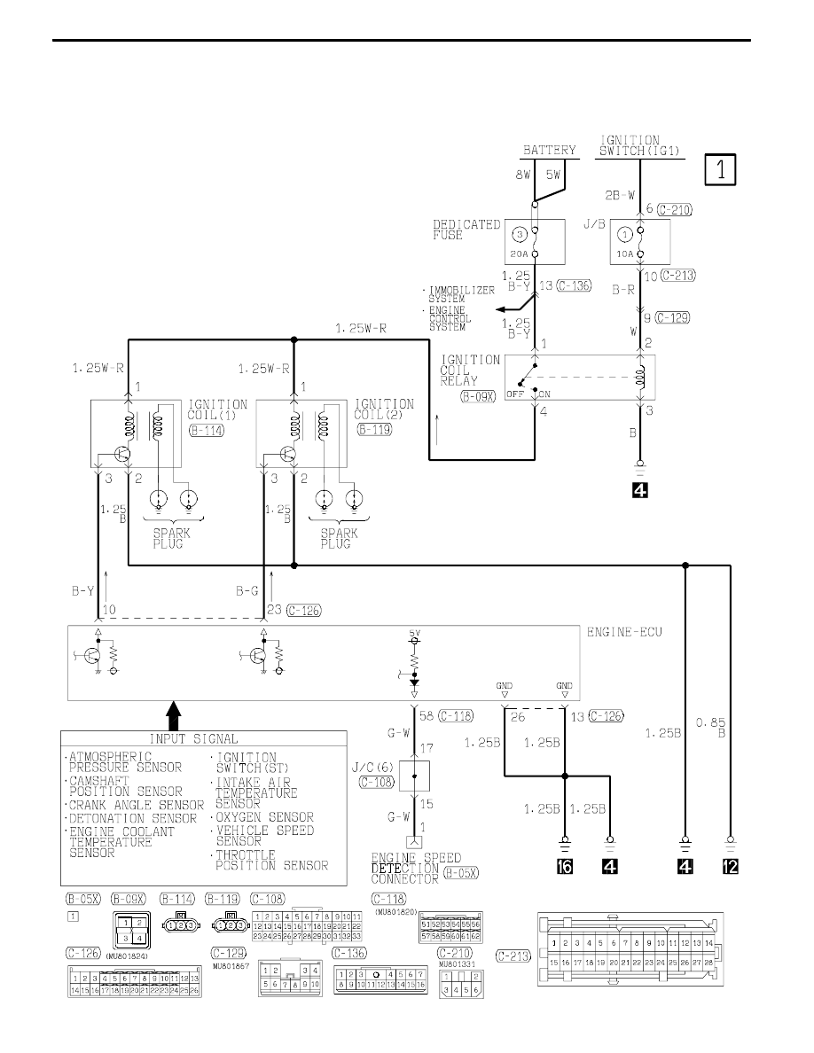
CIRCUIT DIAGRAMS
H1J03X07AA
B-83
IGNITION SYSTEM
R.H. drive vehicles