Mitsubishi Lancer Evolution 7. Manual - part 76
WIRING HARNESS CONFIGURATION DIAGRAMS
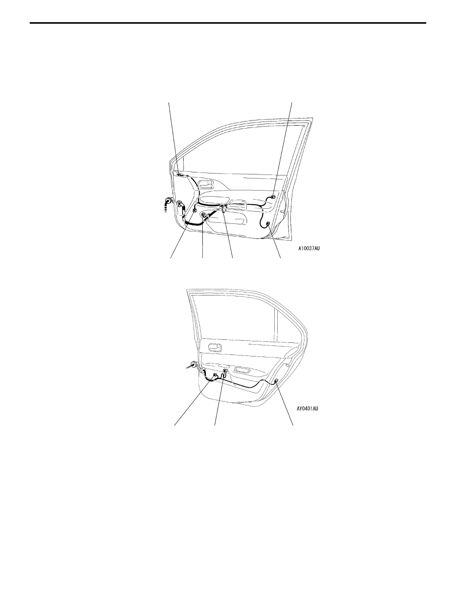
Passenger’s side
Front door
Rear door
E-13
E-16
E-21
E-20
E-19
E-18
E-25
E-24
E-23
Connector colour code
B:Black
Y:Yellow
L:Blue
G:Green
R:Red
BR:Brown
V:Violet
O:Orange
GR:Gray
None: Milk white
B-35
E-16 (3-B)
Door lock key cylinder switch (RH)
E-18 (6-B)
Door lock actuator (Front: RH)
E-19 (8)
Power window sub switch (Passenger’s
side)
E-20 (6-GR)
Power window motor (Front: RH)
E-21 (2)
Spare connector <for front door speaker
(RH)>
E-23 (6-B)
Door lock actuator (Rear: RH)
E-24 (8)
Power window sub switch (Rear: RH)
E-25 (6-GR)
Power window motor (Rear: RH)