Mitsubishi Lancer Evolution 7. Manual - part 75
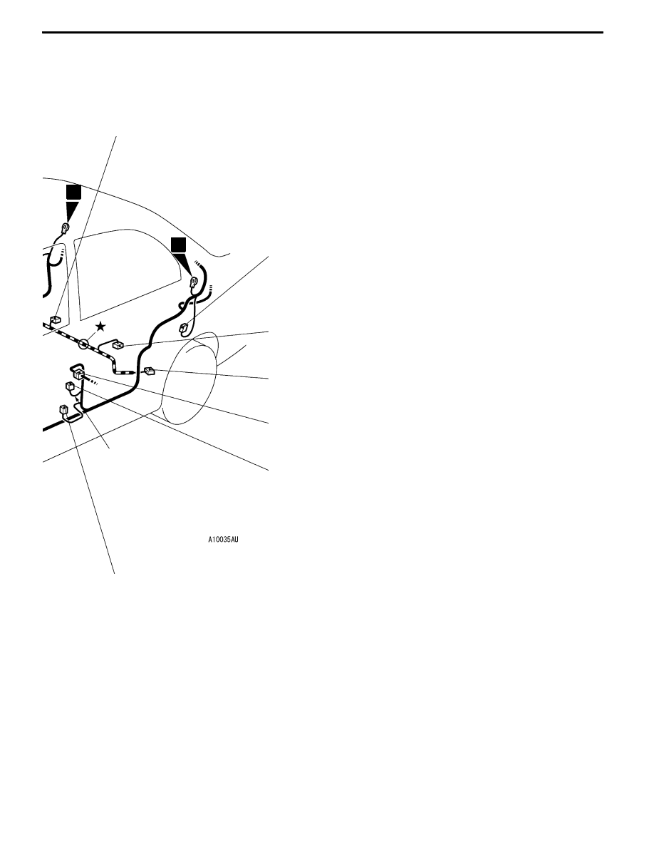
WIRING HARNESS CONFIGURATION DIAGRAMS
D-13
D-27
D-08
D-09
D-10
D-12
D-28
Y
9
10
Connector colour code
B:Black
Y:Yellow
L:Blue
G:Green
R:Red
BR:Brown
V:Violet
O:Orange
GR:Gray
None: Milk white
B-31
D-18 (1)
Cigarette lighter
D-19 (1-B)
Cigarette lighter
D-20 (2-B)
Ashtray illumination lamp
D-21 (2-B)
Cigarette lighter illumination lamp
D-22 (4)
Oxygen sensor (Rear)
D-23 (1-B)
Parking brake switch
D-26 (2-R)
Seat belt pretensioner (RH)
D-27 (2)
Fuel gauge unit (Sub)
D-28 (2-R)
Seat belt pretensioner (LH)
D-29 (1)
Floor wiring harness (RH) and fuel wiring
harness combination
D-30 (8)
Floor wiring harness (RH) and fuel wiring
harness combination
D-32 (3-B)
G sensor (Longitudinal)
D-33 (3-B)
G sensor (Lateral)
D-34 (6)
Intercooler water spray switch