Mitsubishi Lancer Evolution 7. Manual - part 72
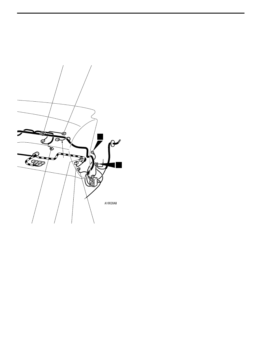
WIRING HARNESS CONFIGURATION DIAGRAMS
C-08
C-16
C-10
C-14
2
3
Y
Connector colour code
B:Black
Y:Yellow
L:Blue
G:Green
R:Red
BR:Brown
V:Violet
O:Orange
GR:Gray
None: Milk white
C-44
C-43
B-19
C-26 (22-B)
J/C (4)
C-29 (22-B)
J/C (5)
C-32 (16-B)
A/C-ECU or heater control unit
C-36 (6-GR)
Headlamp leveling switch
C-41 (22-Y)
SRS-ECU
C-42 (1)
Instrument panel wiring harness and
control wiring harness combination
<ACD>
C-43 (22-Y)
4WD-ECU <ACD>
C-44 (26-Y)
4WD-ECU <ACD>
C-45 (1)
Instrument panel wiring harness and floor
wiring harness (LH) combination