Mitsubishi Lancer Evolution 7. Manual - part 66
HOW TO READ THE WIRING DIAGRAMS -
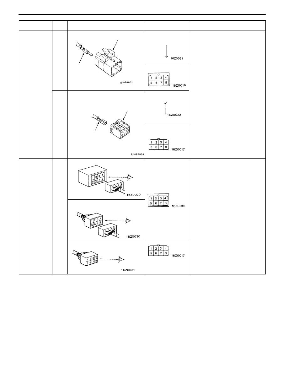
Markings for Connector Earthing
A-7
Item
No.
Connector/Earthing
Symbol
Contents
Connector
and terminal
marking
1
Male connector
Male terminal
The male and female terminals are
indicated as shown. The connector
with male terminal(s) is called as
male connector and indicated by
double connector contour linens,
while the connector with female
Male
terminal
Male connector
while the connector with female
terminal(s) is called as female
connector and indicated by single
connector contour line.
-
Female
connec-
tor
Female terminal
Female
terminal
Female connector
Connector
symbol
marking
2
Device
The symbol indicates the vehicle
connector as viewed from the
illustrated direction. At the connec-
tion with a device, the connector
symbol on the device side is
shown, and for an intermediate
connector, a male connector sym-
bol is shown For spare connectors
Intermediate connector
bol is shown. For spare connectors
and check connectors, no device is
connected, and so the harness-
side connector symbol is shown for
these connectors. The details for
the diagnosis connector differ from
the above description. For details,
refer to the “MUT-II operation
instructions”.
Spare connector, check connector
instructions .