Mitsubishi Lancer Evolution 7. Manual - part 49


  Index      Mitsubishi     Mitsubishi Lancer Evolution 7 - service repair manual


Search            


Content   ..  47  48  49  50   ..


Mitsubishi Lancer Evolution 7. Manual - part 49


BODY CONSTRUCTION -

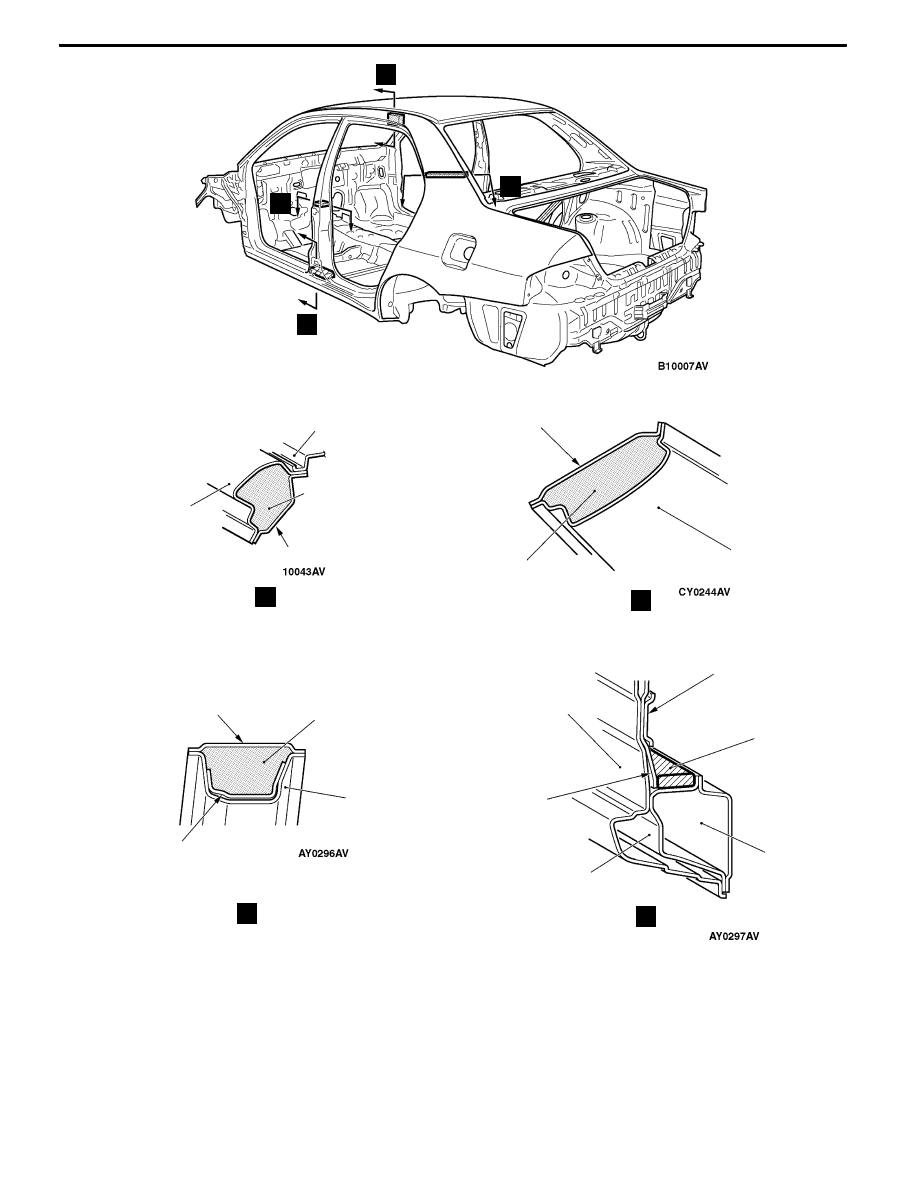
Locations Using Urethane Foam and Foam Material

A-23

E

F

G

E

F

Side outer panel

Rear pillar inner

Side outer

panel

Rear door hinge

reinforcement

upper

Side sill outer

reinforcement

center

Center pillar

reinforcement

Front floor

side sill

inner

Center

pillar inner

Side

outer panel

G

Foam acoustic

material

Foam

acoustic

material

Urethane

foam

Rear door hinge

reinforcement

lower

D

D

Roof panel

Side roof rail inner

Foam

acoustic

material

<RS-II

>

<RS-II>

<RS-II

>

<RS-II

>

BODY CONSTRUCTION -

Stiffener and Dump Sheet Application Locations

A-24

STIFFENER AND DUMP SHEET APPLICATION LOCATIONS

Stiffener is pasted to the inside of the side outer panel, and dump sheets are pasted on the inside

of the front doors to increase surface rigidity, thus improving soundproof qualities with the anti-vibration

effects.

NOTE

The stiffener comes in sheet form and is composed mainly of epoxy resin, glass fibers, and fillers. It hardens

when heated. It is used to improve the rigidity of outer panels.

Stiffener

Dump sheet

<Right side(

RS-II)>

BODY DIMENSIONS -

Body Dimensions and Measurement Methods

B-2

BODY DIMENSIONS AND

MEASUREMENT METHODS

1. Type A (projected dimensions)

Indicates the dimension when a measurement location

is projected onto a plane.

The difference in height of the measurement points should

be taken into consideration when measuring.

2. Type B (actual-measurement dimensions)

Indicates the actual distance between the measurement

points.

Measure using a tracking gauge or a measuring tape,

etc.
NOTE
D

Make the lengths of the tracking gauge probes the

same (A=A’).

D

Do not bend or twist the measuring tape.

3. Insert the tracking gauge probes securely into the

measurement holes

4. When the standard dimensions in the illustration are

enclosed by, this indicates that the symmetrical left and

right positions have the same dimensions.

5. When using a notch for dimension measurement, set

the measuring point at the centre of the notch.

6. When measuring the suspension mounting arm, or link

mounting position, use the suspension mounting bolt,

etc..

7. The body centre points are shown for the purpose of

checking the position of the left and right symmetry

locations.

Height

Probe

Projecteddimension

A’

Actually-measured

dimension

A

Centre

of hole

Bolt

Measuring point


Content   ..  47  48  49  50   ..