Mitsubishi Lancer Evolution 7. Manual - part 26


  Index      Mitsubishi     Mitsubishi Lancer Evolution 7 - service repair manual


Search            


Content   ..  24  25  26  27   ..


Mitsubishi Lancer Evolution 7. Manual - part 26


DRIVE-CONTROL COMPONENTS -

4ABS

3-23

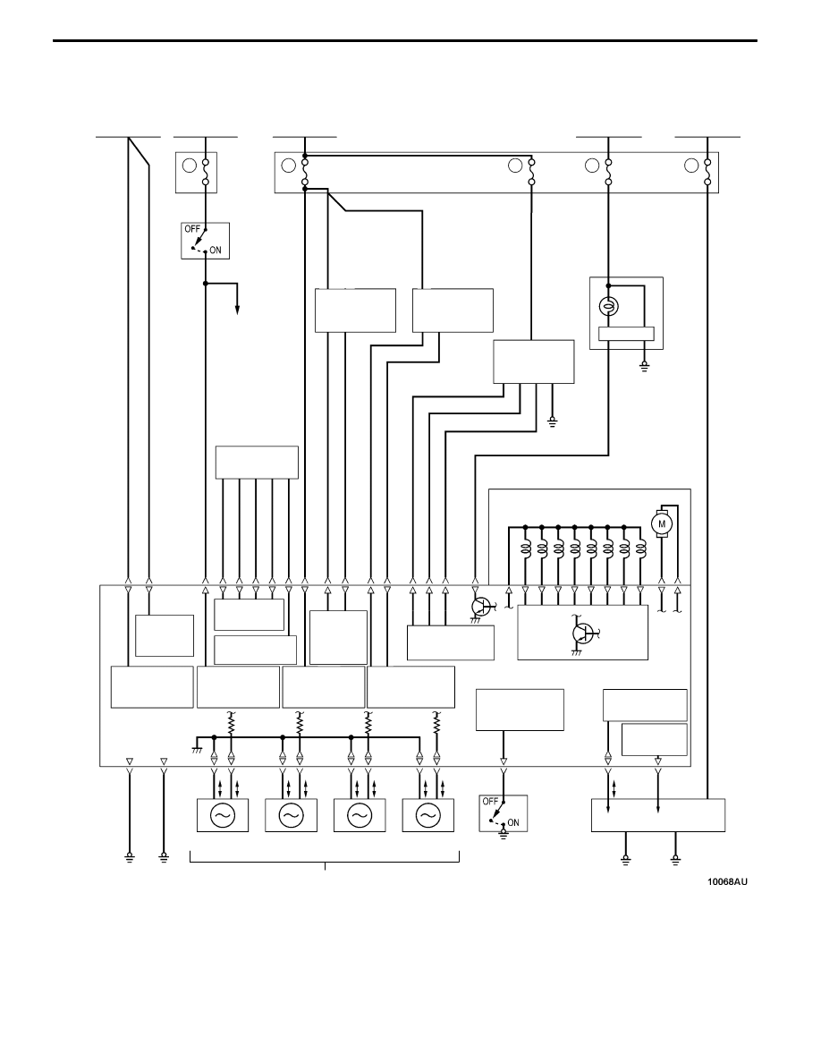
ABS ELECTRICAL CIRCUIT DIAGRAM

5

15A

12

7.5A

15

15A

Ignition Switch

(IG2)

Fusible link

No. 1

Fusible link

No. 3

Battery

Dedicated

fuse

Combination meter

(ABS warning lamp)

Stop lamp

switch

Stop lamp

Motor

Hydraulic unit

Solenoid valves

ABS-ECU

FL

FR

RL

RR

Wheel speed sensor

Diagnosis

connector

Motor power

supply

ECU power

supply

ABS

Stop lamp

switch monitor

Solenoid valve

power supply

Communication

line

Control line

7.5A

Ignition Switch

(IG1)

Junction block (Multi-purpose fuse)

2

ABS

signal output

4WD-ECU

Steering wheel

sensor

7.5A

5

Lateral G sensor

Longitudinal

G sensor

Steering wheel

sensor input

Lateral

G sensor

input

Longitudinal

G sensor

input

Wheel speed

sensor output

Parking brake

switch monitor

Parking brake

switch

DRIVE-CONTROL COMPONENTS -

4ABS

3-24

SENSORS

WHEEL SPEED SENSOR
The wheel speed sensors consist of fixed ABS

speed sensors and the ABS rotors that rotate at

the same speed as the wheels, and output

alternating current signals at frequencies which are

proportional to the wheel speed.

D

The ABS rotors (43 teeth) are installed to the

drive shafts, and the ABS speed sensors are

installed to knuckles.

D

The gap between the ABS rotors and the ABS

speed sensors are non-adjustable at both the

front and rear to improve serviceability.

ABS rotor

ABS speed

sensor

Front

Rear

Drive shaft

ABS rotor

ABS speed

sensor

Drive shaft

LATERAL G SENSOR/LONGITUDINAL G SENSOR
Refer to GROUP 2 - ACD and AYC.

STEERING WHEEL SENSOR
Refer to GROUP 2 - ACD and AYC.

Parking brake lever

Lateral G sensor

Longitudinal G sensor

Steering wheel sensor

DRIVE-CONTROL COMPONENTS -

4ABS

3-25

STOP LAMP SWITCH
This switch turns on when the brake pedal is

depressed, and turns off when the brake pedal

is released. The ABS-ECU detects whether the

stop lamp switch is on or off by means of fluctuations

in voltage (ON: system voltage; OFF: Approximately

0 V). This data is used for ABS control.

PARKING BRAKE SWITCH
This switch turns on when the parking brake lever

is pulled, and turns off when the parking brake

lever is released. The ABS-ECU detects whether

the parking brake switch is on or off by means

of fluctuations in voltage (ON: less than 1V; OFF:

system voltage). This data is used for ABS control.

ACTUATORS

ABS WARNING LAMP
The ABS-ECU controls the power transistor in ABS-ECU to

turn on and causes the ABS warning lamp to illuminate in

the following cases:
D

During initial check when the ignition switch is at the

“ON” position (for approximately 3 seconds)

D

When a problem happens in the ABS/EBD system

D

Poor ABS-ECU connector connection

HYDRAULIC UNIT
The hydraulic unit is basically the same as that of the 1999

PAJERO io <General Export>/2000 PAJERO PININ

<Europe>.

ABS warning lamp

DRIVE-CONTROL COMPONENTS -

4ABS

DRIVE-CONTROL COMPONENTS -

4ABS

3-26

ABS-ECU

The ABS-ECU is basically the same as that of the

1999 PAJERO io <General Export>/2000 PAJERO

PININ <Europe> except for the followings:

FAIL-SAFE FUNCTION

Diagnosis code No

Item

Diagnosis code No.

Item

11

Open circuit or short-circuit in wheel speed sensor (FR)

12

Open circuit or short-circuit in wheel speed sensor (FL)

13

Open circuit or short-circuit in wheel speed sensor (RR)

14

Open circuit or short-circuit in wheel speed sensor (RL)

16

Abnormal drop or rise in ABS-ECU power supply voltage

21

Wheel speed sensor (FR) system

22

Wheel speed sensor (FL) system

23

Wheel speed sensor (RR) system

24

Wheel speed sensor (RL) system

32

Longitudinal G sensor system

41

Solenoid valve (FR) system

42

Solenoid valve (FL) system

43

Solenoid valve (RR) system

44

Solenoid valve (RL) system

51

Valve relay ON problem

52

Valve relay OFF problem

53

Motor relay OFF problem

54

Motor relay ON problem

55

Motor system

63

ABS-ECU abnormality

71

Lateral G sensor system

81

Steering wheel sensor (ST-1) system

82

Steering wheel sensor (ST-2) system

83

Steering wheel sensor (ST-N) system

DATA LIST REFERENCE TABLE

Item No.

Check item

Display unit or words

11

Front-right wheel speed sensor

km/h

12

Front-left wheel speed sensor

13

Rear-right wheel speed sensor

14

Rear-left wheel speed sensor

21

Power supply voltage

V

29

Parking brake switch

ON/OFF

36

Stop lamp switch

ON/OFF

37

Steering wheel sensor straight ahead position memory

ON/OFF


Content   ..  24  25  26  27   ..