Mitsubishi Lancer Evolution 7. Manual - part 23


  Index      Mitsubishi     Mitsubishi Lancer Evolution 7 - service repair manual


Search            


Content   ..  21  22  23  24   ..


Mitsubishi Lancer Evolution 7. Manual - part 23


DRIVE CONTROL COMPONENTS -

Power Steering

DRIVE CONTROL COMPONENTS -

Power Steering

3-11

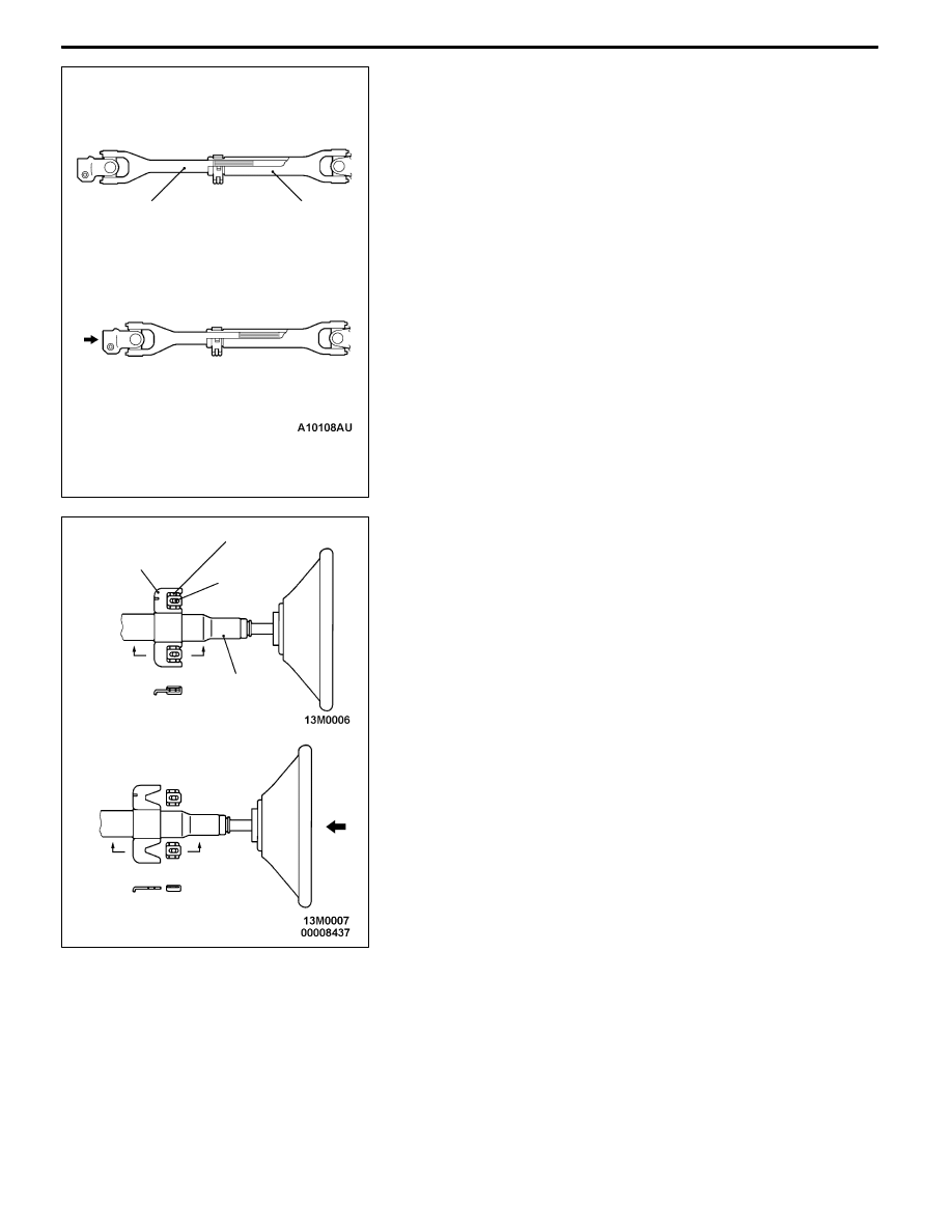
SHOCK ABSORBING MECHANISM
1. Primary impact

When the vehicle collides with something and there is a load
added to the shaft sub assembly from the gearbox, the shaft
sub assembly slides above the pipe sub assembly to absorb
the shock load. This prevents the steering column from
moving backwards during the impact.

2. Secondary impact
(1) When the driver falls against the developed air bag, the

tilt bracket(A) moves forwards by shearing the polyacetal

resin, causing the steering column assembly to move

forward.

BEFORE COLLISION

AFTER COLLISION

Shaft sub assembly

Pipe sub assembly

Tilt bracket(A)

Polyacetal resin

Steering

column

mounting

bolt

Steering

column

assembly

Section A – A

Section B – B

A

A

B

B

Impact

load

BEFORE COLLISION

AFTER COLLISION

DRIVE CONTROL COMPONENTS -

Power Steering

3-12

(2) At the same time that tilt bracket (A) separates, the clevis

pin comes out of the U-section groove in the tilt plate,

allowing the steering column assembly to move forward.

OIL PUMP

The oil pump is a vane type with a fluid flow control

system which functions so that the steering wheel

turning effort will be reduced at low engine speeds

and it will be appropriately increased at higher

speeds.

The following modifications have been made to

Lancer EVOLUTION-VI Tommi Makinen Edition.

D

By increasing the basic discharge amount from

7.2 cm

3

/rev. to 9.6 cm

3

/rev., the assist shortage

at idle has been improved.

D

By increasing the diameter of the pully shaft

bearing and the pump body rigidity , the pump

noise has been relieved reducing vibration

occurance.

POWER STEERING FLUID COOLER TUBE

The cooling efficiency of power steering fluid has been

improved by adopting a cooler tube to the fluid line.

Clevis pin

U-section

groove

Steering column

assembly

Tilt plate

Tilt bracket (B)

BEFORE COLLISION

AFTER COLLISION

Cooler tube

DRIVE CONTROL COMPONENTS -

Power Steering

3-13

STEERING GEAR

D

Using the following parts have contributed to

save weight; an aluminium steering gear and

linkage valve housing, a plastic tie-rod bellows,

and the hollow-type tie-rod stud.

D

The installation accuracy, rigidity and steering

stability have been improved by using an eye

bushing, which secures the steering gear to

the crossmember.

Valve housing

Gear housing

Crossmember

Tierod bellows

Inner pipe

Bushing

Crossmember

Gear housing

Hollow

Steering gear and linkage

DRIVE-CONTROL COMPONENTS -

Brakes

3-14

BRAKES

The brake system has been designed to give

greater reliability and durability and to provide

excellent braking performance.

FEATURES

1. A 4-wheel anti-skid braking system (4ABS) has been

adopted to prevent slipping caused by the vehicle wheels

locking up in order to maintain an appropriate braking

distance, and also to maintain a stable vehicle posture

and steering performance. <Vehicles with ABS>

2. Adoption of an electronic brake-force distribution(EBD)

which makes it possible to maintain the maximum amount

of braking force even when the vehicle’s load is unevenly

distributed. <Vehicles with ABS>

3. A rear wheel early lock-prevention proportioning valve has

been adopted. <Vehicles without ABS>

4. Front- and rear-wheel X-type brake line layout has been

adopted.

5. Ventilated discs have been adopted in order to improve

anti-fading performance.

1. A 8+9-inch brake booster has been adopted to provide

large braking force with a small pedal depression force.

2. 15-inch ventilate disc brakes have been adopted to provide

stable braking force and improved braking feel. <Vehicles

without brembo braking system>

3. 17-inch front ventilate disc brakes have been adopted to

provide stable braking force and improved braking feel.

<Vehicles with brembo braking system>

4. 16-inch rear ventilate disc brakes have been adopted to

provide stable braking force and improved braking feel.

<Vehicles with brembo braking system>

Improved braking perfor-

mance

1. A diagnosis function has been adopted for the ABS system

in order to make inspection easier. <Vehicles with ABS>

2. An outer disc method separated hub and rotor has been

adopted to make removal and installation easier.

3. The master cylinder reservoir tank cap has been coloured

white to make identification easier.

4. The ABS-ECU and hydraulic unit have been integrated

to make them more compact and lightweight.

Improved serviceability

Improved stability


Content   ..  21  22  23  24   ..