Mitsubishi Lancer Evolution 7. Manual - part 17
POWER TRAIN - ACD and AYC
2-21
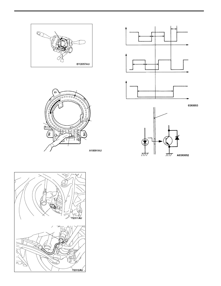
Slit plate
Slit plate
Neutral position
detection slit
Photointerruptor
(ST-1)
Photointerruptor
(ST-2)
Photointerruptor
(ST-N)
Light-emitting diode
Photo-transistor
Zener diode
for disconnec-
tion detection
Slit
Output waveform of each sensor
V
V
V
ST-1
ST-2
ST-N
H
H
H
L
L
L
N (Neutral point)
4°
4°
2°
4°
4°
11°
θ
Steering wheel sensor
θ
θ
WHEEL SPEED SENSOR
Sensor for detecting each wheel speed. It is the same as
that conventionally adopted for the ABS. For vehicle with
ACD
and
AYC,
the
wheel
speed
sensor
signal
waveform-shaped by the ABS-ECU is input to the 4WD-ECU.
<Front>
Wheel speed sensor
<Rear>
Wheel speed sensor