Mitsubishi Lancer Evolution 7. Manual - part 16


  Index      Mitsubishi     Mitsubishi Lancer Evolution 7 - service repair manual


Search            


Content   ..  14  15  16  17   ..


Mitsubishi Lancer Evolution 7. Manual - part 16


POWER TRAIN - ACD and AYC

2-17

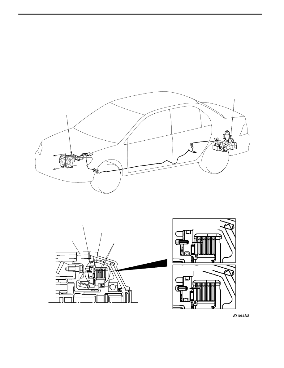
TRANSFER LIMITED SLIP DIFFERENTIAL

During acceleration and deceleration, the piston is moved in the right direction according to the oil pressure

from the hydraulic unit to connect the hydraulic multi plate clutch (friction plate and disc) and set the

center differential to the direct engagement state as much as possible. This improves the acceleration

performance and stability during deceleration.

During turning, the oil pressure from the hydraulic unit stops, the piston operates in the left direction

to release the hydraulic multi plate clutch and free the center differential to improve the turning performance.

If the parking brake is pulled while driving at a vehicle speed above 5 km/h, the hydraulic multi plate

clutch will also be released and the center differential set as close as possible to the free state.

Transfer hydraulic case

Piston

Thrust bearing

Hydraulic multi plate clutch

(Friction plate and disk)

ACD transfer

Hydraulic unit

assembly

A

A

Section A - A

<During acceleration

and deceleration>

<During turning>

POWER TRAIN - ACD and AYC

2-18

HYDRAULIC UNIT

The hydreaulic unit is composed of the accumulator (electric pump, pressure sensor, accumulator) and

pressure controller (proportional valve, directional valve).

The pressure accumulator intermittently operates the pump, and accumulates the control pressure required

in the accumulator.

The pressure controller operates the proportional valve and directional valve, and supplies the appropriate

oil pressure to the ACD transfer or AYC torque transfer differential according to the signals from the

4WD-ECU.
SPECIFICATIONS

Specifications

Specifications

Electric pump

Trochoidal type

Operating oil

ATF SP III

Proportional valve

Current proportional control type

Directional valve

3 position electromagnetic switching method

Wheel speed sensor

Longitudinal G sensor

Lateral G sensor

Steering wheel sensor

4WD-ECU

Engine-ECU

ABS-ECU

ACD mode

indicator lamp

Directional

valve

Proportional

valve (AYC)

Pressure sensor

Electric pump relay

Hydraulic multi

plate clutch

Right

AYC clutch

Accu-

mulator

Electric

pump

Hydraulic unit assembly

Left

ACD transfer

Electronic control system

Oil pressure control system

Parking brake switch

ACD mode switch

Stop lamp switch

TPS

Proportional

valve (ACD)

Proportional valve
Supplies the oil pressure required for ACD or AYC control

according to the instructions of the 4WD-ECU.

Proportional

valve <ACD>

Proportional

valve <AYC>

POWER TRAIN - ACD and AYC

2-19

When the proportional valve is OFF, the oil pressure from

the electric pump will be cut off by the proportional valve.

For this reason, oil pressure will be supplied to the ACD

or AYC and each system will be set into the non-operating

state.

When the proportional valve turns ON, the proportional valve

opens, and the oil pressure from the electric pump will be

supplied to the ACD hydraulic multi plate clutch or AYC

directional valve.

Directional valve
Supplies the oil pressure required for controlling the AYC

clutch according to the instructions of the 4WD-ECU.

When the directional valve is OFF, the oil pressure from the

proportional valve <AYC> will be cut off by the directional

valve. For this reason, the clutch will set into the non-operating

state without oil pressure supplied to each clutch of the AYC.

When oil pressure supply signal for the AYC clutch <Right

side> is sent to the directional valve from the 4WD-ECU,

the directional valve will move to the right. As a result, the

oil pressure from the proportional valve <AYC> will be supplied

to the AYC clutch <Right side>.

If the oil pressure supply signal to the AYC clutch <Left side>

is sent to the directional valve, the directional valve will move

to the left.

From electric pump

Proportional

valve (OFF)

From electric pump

Return

To ACD hydraulic multi plate

clutch or AYC directional valve

Proportional

valve (ON)

Directional

valve

From proportional

valve <AYC>

Directional

valve (OFF)

To clutch

<Right side>

To clutch

<Left side>

From proportional valve

<AYC>

Directional valve

(Right side: ON)

To clutch

<Right side>

To clutch

<Left side>

POWER TRAIN - ACD and AYC

2-20

ELECTRONIC CONTROL SYSTEM

THROTTLE POSITION SENSOR
For detecting the throttle valve opening angle. Also used as throttle position sensor for engine control.

LONGITUDINAL G SENSOR/LATERAL G SENSOR
The longitudinal G sensor are sensors detecting the acceleration in the longitudinal directions of the

vehicle, and are basically the same as those used conventionally.

The lateral G sensor is used for detecting the acceleration along the sides of the vehicle by changing

the installing direction by 90° . The same sensor as the longitudinal G sensor is used.

G-sensor output characteristics

Output voltage (V)

Acceleration speed

(G)

Deceleration speed

(G)

1.0

0

1.0

1.0

1.5

1.5

1.5

2.5

3.5

4.0

Parking brake lever

Lateral G sensor

Longitudinal

G sensor

STEERING WHEEL SENSOR
The steering wheel sensor is installed at the steering column, and is used to output steer angles to

the 4WD-ECU as signals.

It is composed of the slit plate which rotates according to the movements of the handle and a three-set

photointerruptor. The slit plate and photointerruptor have a sealed integrated structure to prevent the

invasion of foreign particles as well as misoperations by external light. To detect malfunctions of the

sensor output circuit, it is equipped with a zener diode for detecting disconnections parallel to the

phototransistor.

The ECU calculates the steering angle by reading the signals of the steering wheel sensor after every

certain period of time and calculating the total of the ST-1 signal and ST-2 signal.

The steering angle is obtained by taking the neutral position (ST-N output is L center) as 0° , and if

there are changes, the steering angle is added with 2° for right and -2° for left. The output of the

photointerruptor becomes L (low) when light passes through and H (high) when obstructed.


Content   ..  14  15  16  17   ..