Mitsubishi Lancer Evolution VI. Manual - part 92


  Index      Mitsubishi     Mitsubishi Lancer Evolution VI - service repair manual


Search            


Content   ..  90  91  92  93   ..


Mitsubishi Lancer Evolution VI. Manual - part 92


SRS  – 

Troubleshooting

52B-14

SRS WARNING LAMP INSPECTION

1.

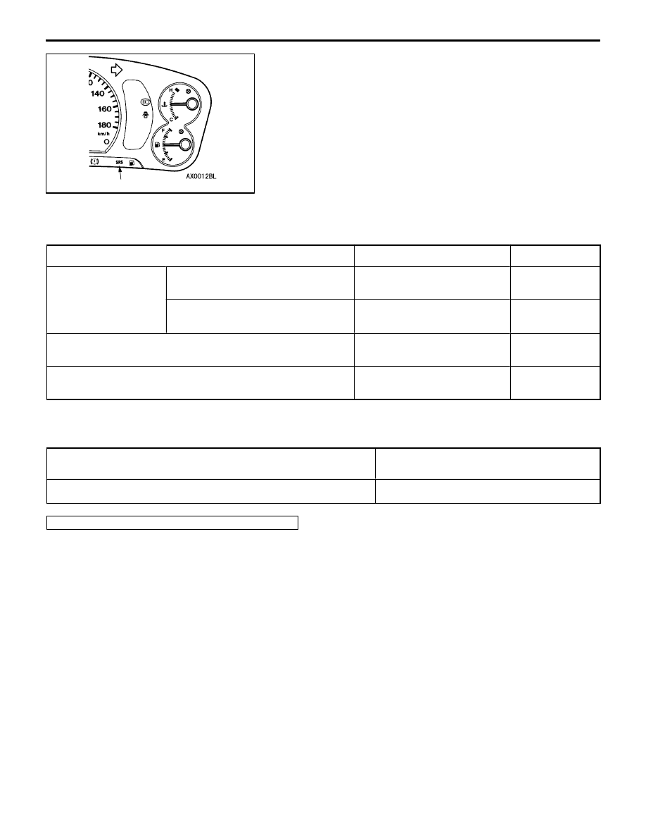
Check to be sure that the SRS warning lamp illuminates
when the ignition switch is in the ON position.

2.

Check to be sure that it illuminates for approximately
7 seconds and then switches off.

3.

If the above is not the cause, inspect the diagnosis codes.

INSPECTION CHART FOR TROUBLE SYMPTOMS

Get an understanding of the trouble symptoms and check according to the inspection procedure chart.

Trouble symptom

Inspection procedure No.

Reference page

Communication with
MUT-

II

 is not possible.

Communication with all systems is not
possible.

1

52B-14

Communication is not possible with
SRS only.

2

52B-15

When the ignition key is turned to “ON” (engine stopped), the
SRS warning lamp does not illuminate.

Refer to diagnosis code No.43.

52B-12

After the ignition switch is turned to ON, the SRS warning lamp
is still on after approximately 7 seconds have passed.

Refer to diagnosis code No.43.

52B-12

INSPECTION PROCEDURE FOR TROUBLE SYMPTOMS

Inspection Procedure 1

Communication with MUT-

II

 is not possible. (Communica-

tion with all systems is not possible.)

Probable cause

The cause is probably a power supply system (including earth circuit) of the diagnosis
line.

D

Malfunction of connectors

D

Malfunction of wiring harness

Refer to GROUP 13A – Troubleshooting.

SRS warning lamp

SRS  – 

Troubleshooting / SRS Maintenance

52B-15

Inspection Procedure 2

Communication with MUT-

II

 is not possible.

(Communication is not possible with SRS only.)

Probable cause

If communication is not possible with the SRS only, the cause is probably an open circuit
in the diagnosis output circuit of the SRS or in the power circuit (including earth circuit).

D

Malfunction of wiring harnesses or connectors

D

Malfunction of SRS-ECU

OK

Check trouble symptoms.

NG

Check the harness wire between the SRS-ECU and earth, and
repair if necessary.

OK

Check trouble symptoms.

NG

Check the harness wire between the SRS-ECU and ignition switch
IG

1

, and repair if necessary.

Measure at SRS check harness
connector (5).

D

Disconnect SRS-ECU 
connector B-51.

D

Connect SRS check 
harness connector (3).

D

Continuity between 
terminals (20)
OK: Continuity

NG

Check the following
connectors:
B-51, B-78, B-80

NG

Repair

SRS check harness
(MB991613)

3

5

OK

Replace the SRS-ECU.

OK

Check the harness wire between the SRS-ECU and diagnosis
connector.

NG

Repair

OK

Measure at SRS check harness connector (5).

D

Disconnect SRS-ECU connector B-51.

D

Connect SRS check harness connector (3).

D

Ignition switch: ON

D

Voltage between terminal (13) and body earth
OK: 9 V or more

D

Voltage between terminal (14) and body earth
OK: 9 V or more

NG

Check the following
connectors:
B-51, B-78, B-76

NG

Repair

SRS MAINTENANCE

The SRS must be inspected by an authorized dealer 10 years
after the date of vehicle registration.

SRS WARNING LAMP CHECK

Turn the ignition key to the “ON” position. Does the SRS
warning lamp illuminate for about 7 seconds, turn off and
then remain extinguished for at least 5 seconds? If yes, SRS
system is functioning properly. If no, consult page 52B-6.

SRS warning lamp

SRS  – 

SRS Maintenance

52B-16

SRS COMPONENT VISUAL CHECK

Turn the ignition key to the LOCK (OFF) position, disconnect
the negative battery cable and tape the terminal.

Caution
Wait at least 60 seconds after disconnecting the battery
cable before doing any further work. (Refer to P.52B-3.)

SRS CONTROL UNIT (SRS-ECU)

1.

Check SRS-ECU case and brackets for dents, cracks,
deformation or rust.

Caution
The SRS may not activate if the SRS-ECU is not
installed properly, which could result in serious injury
or death to the vehicle’s driver or front passenger.

2.

Check connector for damage, and terminals for
deformation or rust.
Replace SRS-ECU if it fails visual check.
(Refer to P.52B-24.)

AIR BAG MODULES, STEERING WHEEL AND CLOCK
SPRING

1.

Remove the air bag modules, steering wheel and clock
spring. (Refer to P.52B-25.)

Caution
The removed air bag modules should be stored in
a clean, dry place with the pad cover face up.

2.

Check pad cover for dents, cracks or deformation.

Insulating tape

Battery

Battery (–) cable

SRS-ECU

Pad cover

<Driver’s side>

<Front passenger’s side>

Pad cover

SRS  – 

SRS Maintenance

52B-17

3.

Check connector for damage, terminals deformities, and
harness for binds.

4.

Check air bag inflator case for dents, cracks or deformities.

5.

Check harness and connectors for damage, and terminals
for deformation.

6.

Check clock spring connectors and protective tube for
damage, and terminals for deformation.

7.

Visually check the clock spring case for damage.

8.

Align the mating marks of the clock spring and, after
turning the vehicle’s front wheels to straight-ahead
position, install the clock spring to the column switch.

Mating Mark Alignment

Turn the clock spring clockwise fully, and then turn back
it approx. 3 4/5 turns counterclockwise to align the mating
marks.

Caution
If the clock spring’s mating mark is not properly
aligned, the steering wheel may not be completely
rotational during a turn, or the flat cable within the
clock spring may be severed, obstructing normal
operation of the SRS and possibly leading to serious
injury to the vehicle’s driver or front passenger.

9.

Install the steering column covers, steering wheel and
the air bag module.

10. Check steering wheel for noise, binds of difficult operation.
11. Check steering wheel for excessive free play.

REPLACE ANY VISUALLY INSPECTED PART IF IT
FAILS THAT INSPECTION. (Refer to P.52B-25.)

Caution
The SRS may not activate if any of the above
components is not installed properly, which could
result in serious injury or death to the vehicle’s driver
or front passenger.

<Driver’s side>

Inflator case

Connector

<Front passenger’s side>

Inflator case

Connector

Protective tube

Case

Mating marks

Protective tube


Content   ..  90  91  92  93   ..