Mitsubishi Lancer Evolution VI. Manual - part 93
SRS –
SRS Maintenance
52B-18
BODY WIRING HARNESS
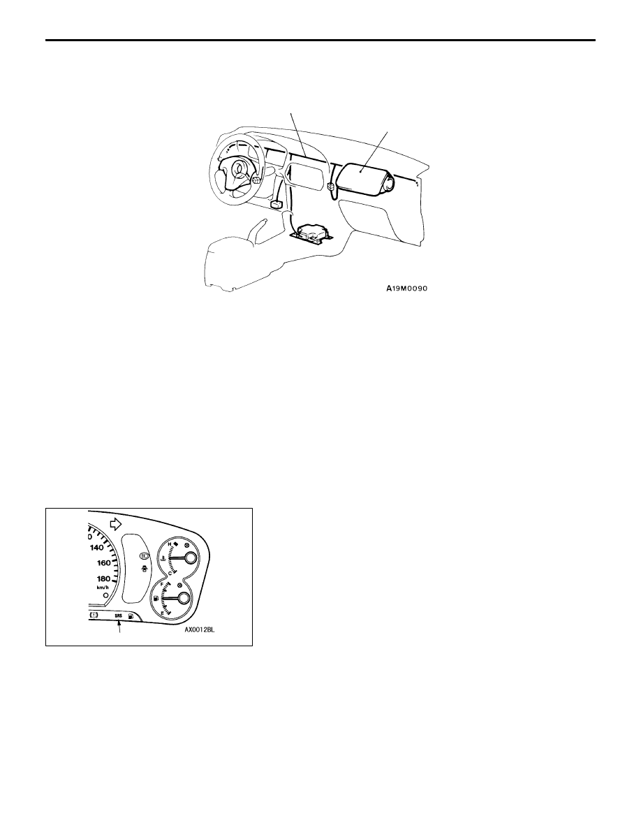
*
Body wiring harness
NOTE
*: Vehicles with front passenger’s air bag
1.
Check connector for poor connection.
2.
Check harnesses for binds, connectors for damage, and
terminals for deformation.
REPLACE ANY CONNECTORS OR HARNESS THAT
FAIL THE VISUAL INSPECTION. (Refer to P.52B-3.)
Caution
The SRS may not activate if SRS harnesses or
connectors are damaged or improperly connected,
which could result in serious injury or death to the
vehicle’s driver or front passenger.
POST-INSTALLATION INSPECTION
Reconnect the negative battery terminal. Turn the ignition
key to the “ON” position. Does the SRS warning lamp illuminate
for about 7 seconds, turn off and then remain extinguished
for at least 5 seconds? If yes, SRS system is functioning
properly. If no, consult page 52B-6.
SRS warning lamp