Mitsubishi Lancer Evolution VI. Manual - part 82


  Index      Mitsubishi     Mitsubishi Lancer Evolution VI - service repair manual


Search            


Content   ..  80  81  82  83   ..


Mitsubishi Lancer Evolution VI. Manual - part 82


BODY – 

General / Keyless Entry System

42-2

GENERAL

OUTLINE OF CHANGE

D

The descriptions of the troubleshooting using on MUT-

II

 tester have been incorporated.

KEYLESS ENTRY SYSTEM
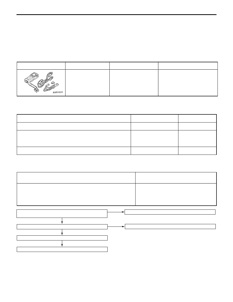
SPECIAL TOOL

Tool

Number

Name

Use

MB991502

MUT-

II

 sub assembly

Recording secret codes

TROUBLESHOOTING

INSPECTION CHART FOR TROUBLE SYMPTOMS

Trouble symptom

Inspection procedure No.

Reference page

None of the doors can be locked or unlocked using the transmitter.

1

42-2

All of the doors can be locked and unlocked using the transmitter,
but the room lamp does not flash or illuminate. (However, the room
lamp operates normally when the doors are opened and closed.)

2

42-4

Secret codes cannot be registered.

3

42-4

INSPECTION PROCEDURE FOR TROUBLE SYMPTOMS

INSPECTION PROCEDURE 1

None of the doors can be locked or unlocked using the
transmitter.

Probable cause

The cause may be a malfunction of the transmitter, a malfunction of the receiver
or the lock and unlock signals are not being input to the ETACS-ECU.

D

Malfunction of transmitter

D

Malfunction of receiver

D

Malfunction of ETACS-ECU

D

Malfunction of wiring harness or connector

D

Malfunction of key reminder switch

D

Malfunction of door switch

NG

To next page

OK

Replace the transmitter battery. (Refer to P.42-7.)

Yes

Has the secret code been registered properly? *

NG

Re-register the secret code. (Refer to P.42-8.)

Can the doors be locked and unlocked by the driver’s-side door
key cylinder and lock knob?

No

Check the centre door lock system.

NOTE
*: This should be done if a transmitter or receiver has been replaced, and if a secret code has not
been registered properly.

BODY  – 

Keyless Entry System

42-3

NG

Repair

NG

Check the harness wire, and repair if necessary.

D

Between receiver and earth

NG

Repair

OK

Replace the ETACS-
ECU.

NG

Repair

OK

Replace the transmitter.

NG

Replace the receiver.

NG

Check the harness wire.

D

Between key reminder switch and receiver

D

Between key reminder switch and earth

NG

Repair

OK

Check trouble symptoms.

OK

Check the following connectors:
B-50, B-84, D-01

NG

Repair

OK

Key reminder switch continuity check (Refer to GROUP 54 – Ignition
Switch.)

NG

Replace

NG

Check the harness wire.

D

Between receiver and door switch

NG

Repair

OK

Check trouble symptoms.

OK

Check the following connectors:
D-01, D-03, D-06, D-17, F-12, F-26

NG

Repair

NG

Check the harness wire.

D

Between ETACS-ECU and receiver

OK

Door switch continuity check

NG

Replace

OK

Check trouble symptoms.

OK

Measure at the receiver connector D-01.

D

Disconnect the connector, and measure at harness side.

D

Voltage between 12 and body earth

D

Voltage between 14 and body earth
OK: System voltage

NG

Check the connectors:
B-77, D-01

OK

Check trouble symptoms.

OK

Measure at the receiver connector D-01.

D

Disconnect the connector, and measure at the harness side.

D

Continuity between 20 and body earth
OK: Continuity

NG

Check the following connectors:
B-50, D-01

NG

Repair

NG

Check the harness wire, and repair if necessary.

D

Between ignition switch and receiver

D

Between fusible link No.1 and receiver

OK

Check trouble symptoms.

Measure at the receiver connector D-01.

D

Disconnect the connector, and measure at the harness side.

D

Voltage between 9 and body earth

D

Voltage between 10 and body earth
OK: System voltage

NG

Check the following connectors:
B-49, B-73, B-75, B-76

From previous page

BODY  – 

Keyless Entry System

42-4

INSPECTION PROCEDURE 2

All of the doors can be locked and unlocked using the
transmitter, but the room lamp does not flash or
illuminate. (However, the room lamp operates normally
when the doors are opened and closed.)

Probable cause

If the room lamp operates normally when the doors are opened and closed, the cause
of the problem may be a malfunction of the receiver or a malfunction of the harness
between the room lamp the receiver.

D

Malfunction of receiver

D

Malfunction of connector or wiring harness

NG

Repair

NG

Check the harness wire between room lamp and receiver, and
repair if necessary.

OK

Replace the receiver.

OK

Check trouble symptoms.

Measure at the receiver connector D-01.

D

Disconnect the connector, and measure at the harness side.

D

Voltage between 11 and body earth
OK: System voltage

NG

Check the following connectors:
B-80, D-01

INSPECTION PROCEDURE 3

Secret codes cannot be registered.

Probable cause

The cause may be a malfunction of the diagnosis connector, a malfunction of the
power supply or earth circuit of the receiver, a malfunction of the earth circuit or
a malfunction of the diagnosis output circuit.

D

Malfunction of receiver

D

Malfunction of MUT-

II

D

Malfunction of connector or wiring harness

NG

Repair

NG

Check the harness wire, and repair if necessary.

D

Between receiver and diagnosis connector

NG

Repair

NG

Check the harness wire, and repair if necessary.

D

Between fusible link No.1 and diagnosis connector

OK

Check trouble symptoms.

NG

Check the harness wire, and repair if necessary.

D

Between diagnosis connector and earth

Yes

To next page

NG

Check the following
connectors:
B-22, B-50

NG

Repair

OK

Measure at the diagnosis
connector B-22.

D

Continuity between  4
and body earth

D

Continuity between 5
and body earth
OK: Continuity

OK

Replace MUT-

II

.

OK

Check trouble symptoms.

No

Measure at the diagnosis
connector B-22

D

Voltage between 16
and body earth
OK: System voltage

NG

Check the following connectors:
B-22, B-49, B-75

OK

Can the MUT-

II

 communicate with other systems?

OK

Check trouble symptoms.

Measure at the diagnosis connector B-22 and the receiver connector
D-01.

D

Disconnect the connector, and measure at harness side.

D

Continuity between following terminals:
OK: Continuity

7 <Receiver side> – 1 <Diagnosis connector side>

NG

Check the following connectors:
B-22, D-01

BODY  – 

Keyless Entry System

42-5

NG

Repair

NG

Check the harness wire, and repair if necessary.

D

Between fusible link No.1 and receiver

D

Between ignition switch and receiver

NG

Repair

NG

Check the harness wire, and repair if necessary.

D

Between receiver and earth

OK

Replace the receiver.

OK

Check trouble symptoms.

OK

Measure at the receiver connector D-01.

D

Disconnect the connector, and measure at the harness side.

D

Between 20 and body earth
OK: Continuity

NG

Check the following connectors:
B-50, D-01

OK

Check trouble symptoms.

Measure at the receiver connector D-01.

D

Disconnect the connector, and measure at the harness side.

D

Voltage between 9 and body earth

D

Voltage between 10 and body earth
OK: System voltage

NG

Check the following connectors:
B-49, B-75, D-01

From previous page

INSPECTION OF RECEIVER TERMINAL VOLTAGE

Terminal

Signal name

Conditions

Terminal voltage

2

Door switch

One or more doors are open (Door switch: ON)

0 V

All doors are closed (Door switch: OFF)

System voltage

6

Door lock actuator
switch (driver’s side)

LOCK

5 V and pulse output*

switch (driver’s side)

UNLOCK

0 V

7

Diagnosis changeover
input

When MUT-

II

 is connected

0 V

input

When MUT-

II

 is disconnected

System voltage

8

Key reminder switch

OFF (When ignition key is inserted)

5 V and pulse output*

ON (When ignition key is removed)

0 V

9

Ignition switch

Ignition switch: ACC or ON

System voltage

Ignition switch: OFF

0 V

10

Receiver power supply

At all times

System voltage

11

Room lamp output

One or more door are open (Door switch: ON)

0 V

All doors are closed (Door switch: OFF)

System voltage


Content   ..  80  81  82  83   ..