Mitsubishi Lancer Evolution VI. Manual - part 80
STEERING –
Power Steering Gear Box
37A-12
REASSEMBLY SERVICE POINTS
"
A
A
GEAR HOUSING MOUNTING RUBBER
INSTALLATION
1.
Install the gear housing mounting rubber on the rack
housing so that the dimension shown is achieved.
NOTE
The gear housing mounting rubber can be installed
regardless of the installation direction of the slit.
2.
Apply specified adhesive to the slit of the gear housing
mounting rubber.
Specified adhesive:
3M ATD Part No. 8155 or equivalent
"
B
A
OIL SEAL INSTALLATION
"
C
A
NEEDLE ROLLER BEARING / BALL BEARING
INSTALLATION
"
D
A
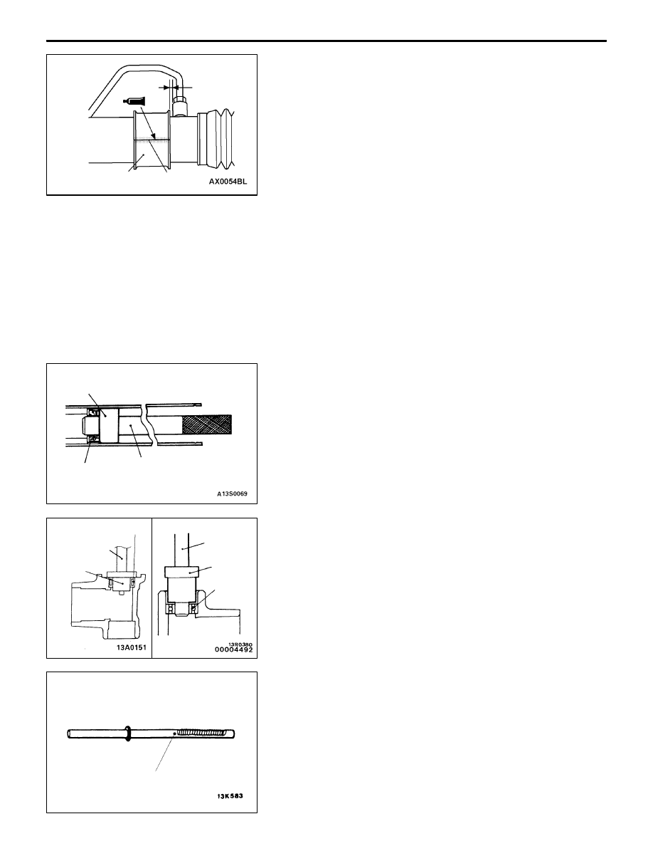
RACK INSTALLATION
1.
Apply a coating of repair kit grease to the rack tooth
face.
Caution
Do not close the vent hole in the rack with grease.
Slit
Gear housing
mounting rubber
3.1 mm
MB991452
Oil seal
MB991197
(Bar)
Needle roller
bearing
MB990938
MB991202
MB990938
MB991202
Ball bearing
Vent hole