Mitsubishi Lancer Evolution VI. Manual - part 60


  Index      Mitsubishi     Mitsubishi Lancer Evolution VI - service repair manual


Search            


Content   ..  58  59  60  61   ..


Mitsubishi Lancer Evolution VI. Manual - part 60


REAR AXLE

  – On-vehicle Service <Vehicles with AYC>

REAR AXLE

  – On-vehicle Service <Vehicles with AYC>

27-34

BLEEDING

1.

Lift up the vehicle.

2.

Connect the MUT-

II

 to the 16-pin diagnosis connector.

Caution 
Before connecting or disconnecting the MUT-

II

,

always turn off the ignition switch.

3.

Turn on the ignition switch.

4.

Operate the MUT-

II

 (Item No.10) to activate the hydraulic

unit forcibly.

NOTE
(1) The forced activation (air bleeding mode) will be

automatically canceled after 5 minutes operation. It
can also be canceled forcibly by operating the clear
key on the MUT-

II

.

(2) While this function is being disabled by the fail-safe

function, the forced activation of the hydraulic unit
can not be executed.

5.

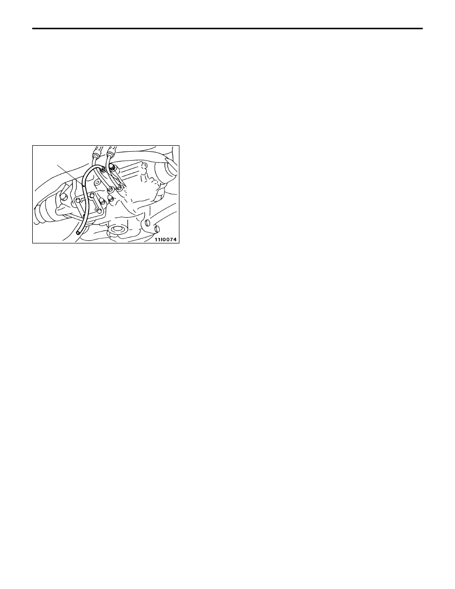
Remove the cap of the left bleeder screw on the torque
transfer differential and connect a vinyl hose.

6.

Gradually turn the steering wheel clockwise from the
straight-ahead position. At this time, loosen the left bleeder
screw and check that fluid is discharged with air.

7.

After air has been completely discharged, tighten the
bleeder screw.

Caution
While the system is being bled of air, add fluid as
necessary to ensure that it is left in the oil reservoir
during the entire procedure.

8.

Repeat steps (6) and (7) two to three times until no air
bubbles are recognized in the fluid that comes out. Then,
tighten the bleeder screw to the specified torque.

Tightening torque: 9 Nm

9.

Perform steps (5) through (8) for the right bleeder screw.
Note, however, that the steering wheel should be turned
counterclockwise.

10. After the system has been completely bled of air, check

for the fluid level. (Refer to P.27-33.)

Caution
If the system is not completely bled of air, the hydraulic
unit could generate noise, degrading pump durability.

AYC OPERATION CHECK

1.

Lift up the vehicle.

2.

Connect the MUT-

II

 to the 16-pin diagnosis connector.

Caution
Before connecting or disconnecting the MUT-II, always
turn off the ignition switch.

3.

Start the engine.

4.

Operate the MUT-

II

 with the transmission in 2nd or a

higher gear and check to ensure that the vehicle speed
is higher than 10 km/h using the Data List (Item 10).

Bleeder
screws

Vinyl hose

REAR AXLE

  – On-vehicle Service <Vehicles with AYC>

27-35

NOTE
(1) Hold the steering wheel in the neutral position.
(2) If the steering wheel is turned, it may happen that

the AYC system continues to operate (operation
sounds are heard from the torque transfer differential).
However, it does not mean a system failure. If such
a case is encountered, perform the following
operations with the steering wheel in the neutral
position to cancel the AYC function.

D

Disengage the clutch.

D

Set the transmission to neutral.

D

Stop the engine.

5.

Operate the MUT-

II

 (Item Nos.13 and 14) to activate

the torque transfer differential.

NOTE
(1) The forced activation (clutch operation mode) will be

automatically canceled after 1 minute operation.
It can also be canceled forcibly by operating the clear
key on the MUT-

II

.

(2) While this function is being disabled by the fail-safe

function, the forced activation of the torque transfer
differential can not be executed.

6.

Operate the MUT-

II

 to confirm that the several speeds

of the wheels are as shown below, using the Data List
(Item Nos.07 and 08).

<Forced activation Item No.13 is being executed>
The speed of left rear wheel is more than 2 km/h
higher than that of right rear wheel.
<Forced activation Item No.14 is being executed>
The speed of right rear wheel is more than 2 km/h
higher than that of left rear wheel.

NOTE
If the above requirements are not satisfied, the system
is probably failed. Check the hydraulic pressure.

HYDRAULIC PRESSURE CHECK

1.

Lift up the vehicle.

2.

Connect the MUT-

II

 to the 16-pin diagnosis connector.

Caution
Before connecting or disconnecting the MUT-

II

,

always turn off the ignition switch.

3.

Turn on the ignition switch.

4.

Disconnect the joint between the hydraulic unit and the
hydraulic unit hose assembly. Connect the special tool
to the L port. To the R port, attach a blind plug or connect
the L port of the removed hydraulic unit hose assembly.

5.

Operate the MUT-

II

 (Item No.13) to activate the hydraulic

unit.

NOTE
(1) The forced activation (clutch left side operation check

mode) will be automatically canceled after 1 minute
operation.
It can also be canceled forcibly by operating the clear
key on the MUT-

II

.

MB991705

MD998330

REAR AXLE

  – On-vehicle Service <Vehicles with AYC>

27-36

(2) While this function is being disabled by the fail-safe

function, the forced activation of the hydraulic unit
can not be executed.

6.

Check to ensure that the hydraulic pressure generated
by the hydraulic unit conforms to the standard value.

Standard value: 1.0 – 1.6 MPa

NOTE
During checking the hydraulic pressure, occasionally
replenish the oil reservoir with fluid so that it does not
become empty.

7.

Check the hydraulic pressure of the clutch right side by
repeating the steps (4) through (6). At this time, however,
the special tool must be connected to the R port and
the blind plug or the R port of the removed hydraulic
unit hose assembly must be attached to the L port. Further,
the MUT-

II

 must be operated in the forced activation mode

Item No. 14 (clutch right side operation check mode).

8.

If the measured value exceeds the standard value, replace
the hydraulic unit.

9.

Connect the hydraulic unit hose assembly to the hydraulic
unit and to the torque transfer differential and tighten
the flare nuts to the specified torque.

Specified torque: 34 Nm

10. Pour the specified fluid in the oil reservoir up to the MAX

mark. Then, bleed the system.

Specified fluid: Dia Queen ATF SP 

II

 or equivalent

Fluid amount used: Approx. 1 

ȏ

DIFFERENTIAL CARRIER OIL SEAL
REPLACEMENT

DIFFERENTIAL

1.

Remove the drive shaft.

2.

Remove the oil seal from the differential carrier.

3.

Using the special tool, drive a new oil seal all the way
into position.

4.

Coat the oil seal lips and the drive shaft surface in contact
with the oil seal with multi-purpose grease.

5.

Replace the drive shaft circlip with a new one and mount
the drive shaft to the differential carrier.

6.

Check for correct wheel alignment.

TORQUE TRANSFER MECHANISM

1.

Remove the drive shaft.

2.

Remove the oil seal from the differential carrier.

3.

Using the special tool, drive a new oil seal all the way
into position.

4.

Coat the oil seal lips and the drive shaft surface in contact
with the oil seal with the specified grease.

Specified grease: Vaseline

5.

Replace the drive shaft circlip with a new one and mount
the drive shaft to the differential carrier.

6.

Check for correct wheel alignment.

MB990938

MB991115

MD998829

MD998812

MD998813

REAR AXLE

  – On-vehicle Service <Vehicles with AYC>

27-37

WHEEL SPEED SENSOR OUTPUT VOLTAGE
MEASUREMENT <VEHICLES WITHOUT ABS>

1.

Lift up the vehicle and release the parking brake.

2.

Disconnect the AYC-ECU harness connector and take
measurements on the harness side connector.

Caution
Insert the probe from the harness side with the double
lock of the connector unlocked. Inserting it to the
terminal side could result in poor contact.

3.

Turn the wheel to be tested at about 1/2 to one
revolution/sec. and check for the output voltage using
a circuit tester (AC mV range) or oscilloscope.

Terminal nos.

Front LH

Front RH

Rear LH

Rear RH

7

6

9

8

20

19

22

21

Output voltage: 

When circuit tester is used: 70 mV or more 
When oscilloscope is used: 200 mVp-p or more

(4) If the output voltage is lower than the above value, it

is probably attributable to the following faults. Check or
replace the wheel speed sensor as necessary.

D

Excessive clearance between the pole piece and rotor
of the wheel speed sensor

D

Defective wheel speed sensor

Waveform Check Using Oscilloscope

Check the harness and connector of the wheel speed sensor
for connection. Then, use an oscilloscope to check for output
voltage waveform of each sensor as follows.
Start the engine and monitor the sensor by turning the wheel;
for a driving wheel, let it turn by shifting into the 1st gear
and for a driven wheel turn it manually at a constant speed.

NOTE
(1) Waveform may be observed by actually running the

vehicle.

(2) The output voltage is low when the wheel speed remains

low and builds up as the wheel speed increases.

AYC-ECU connector harness side

When turned manually

At idle (5 to 6 km/h)
1st gear


Content   ..  58  59  60  61   ..