Mitsubishi Lancer Evolution VI. Manual - part 17


  Index      Mitsubishi     Mitsubishi Lancer Evolution VI - service repair manual


Search            


Content   ..  15  16  17  18   ..


Mitsubishi Lancer Evolution VI. Manual - part 17


ENGINE  – 

Cylinder Head and Valves

11-43

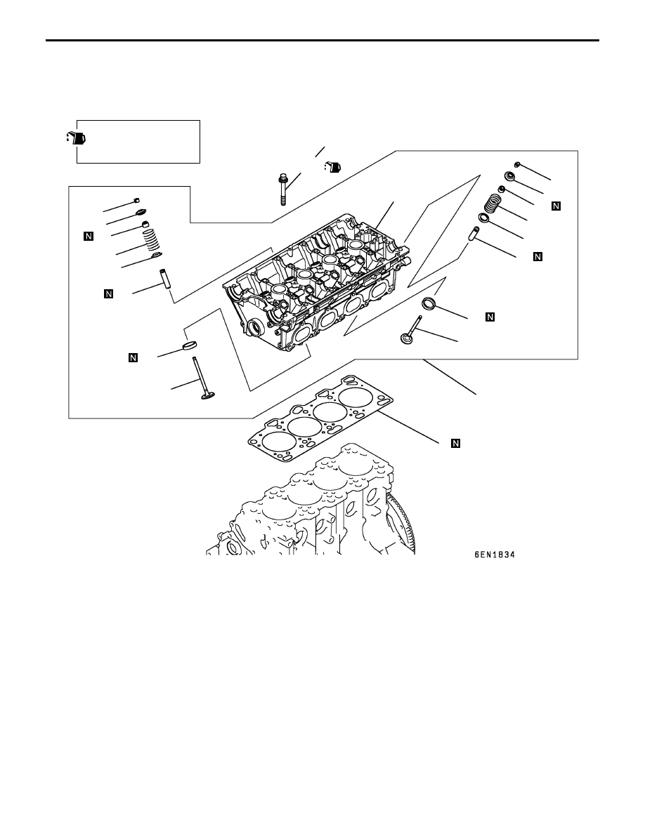
CYLINDER HEAD AND VALVES

REMOVAL AND INSTALLATION

Apply engine oil to all
moving parts before
installation.

78 Nm 

 Loosen completely 

 20 Nm + 90

_

 + 90

_

1

2

3

4

5

6

7

8

9

10

11

12

13

14

15

16

17

18

19

20

Removal steps

A

A

" "

D

A

1. Cylinder head bolt
2. Cylinder head assembly
3. Cylinder head gasket

A

B

" "

C

A

4. Retainer lock
5. Valve spring retainer

"

B

A

6. Valve spring
7. Intake valve

A

B

" "

C

A

8. Retainer lock
9. Valve spring retainer

"

B

A

10. Valve spring

A

C

"

11. Exhaust valve

"

A

A

12. Valve stem seal
13. Valve spring seat

"

A

A

14. Valve stem seal
15. Valve spring seat
16. Intake valve guide
17. Exhaust valve guide
18. Intake valve seat
19. Exhaust valve seat
20. Cylinder head

ENGINE  – 

Cylinder Head and Valves

11-44

REMOVAL SERVICE POINTS

PRECAUTION FOR REMOVED PARTS

Keep removed parts in order according to the cylinder number
and intake/exhaust.

A

A

"

CYLINDER HEAD BOLTS REMOVAL

Using the special tool, loosen the cylinder head bolts. Loosen
evenly, little by little.

A

B

"

RETAINER LOCK REMOVAL

Store removed valves, springs and other parts, tagged to
indicate their cylinder No. and location for reassembly.

A

C

"

VALVE HANDLING PRECAUTIONS

(1) Sodium reacts violently with water or moisture generation

heat and liberating hydrogen. It must be handled with
utmost care because otherwise the following dangerous
conditions may result:
Loss of eyesight if sodium gets in eyes.
Burns if soduim contact skin.
Fire hazard.

(2) Handling of Soduim-filled Exhaust Valves

Soduim-filled exhaust valves are not dangerous and may
be handled in the same way as ordinary valves unless
they are broken.
Never try to break the valves and expose soduim to the
air. When worn exhaust valves are to be discarded, have
them disposed of by a salvage company equipped with
special disposal system, notifying them that the valves
contain soduim.
Should the exhaust valves be broken, neutralize soduim
using the method described below, and discard the valves
in the same way as ordinary valves.

MB991654

MD998772

MD998735

ENGINE  – 

Cylinder Head and Valves

11-45

(3) How to Neutralize Sodium

Place a container filled with more than 10 liters of water
in a well ventilated large space.
Wear rubber gloves and goggles, and carefully take out
broken valves from the cylinder head.
Put a broken valve in the water-filled container and quickly
get away from the container at least 2 or 3 m.

Caution
1.

Valves must be neutralized one at a time.

2.

Put a valve in the container only after soduim
in the preceding one has completely reacted with
water.

Keep fire away from the container during the
neutralization. The resulting hydrogen gas is highly
explosive.
When the reaction has finished (there is no more
generation of hydrogen gas), take the valves out of the
container with large tweezers or the like.

NOTE
The reaction occurs when water enters the cavity in the
valve. Hydrogen gas may be trapped inside the valve,
temporarily blocking the water passage. In such a case,
wait until hydrogen gas in released and remaining soduim
reacts with water.
After the neutralization of soduim, water in the container
contains soduim hydroxide and is highly alkaline. The
water solution should be disposed of according to local
regulations.

Caution
1.

Do not let the solution contact the eyes or the
skin.

2.

Should it get in the eyes, immediately flush them
with clean water thoroughly, and receive medical
attention. When it contacts the skin, wash with
ample amounts of clean water.

INSTALLATION SERVICE POINTS

"

A

A

VALVE STEM SEAL INSTALLATION

(1) Install the valve spring seat.
(2) The special tool must be used to install the valve stem

seal. Improper installation could result in oil leaks past
the valve guide.

Caution
Do not reuse removed valve stem seals.

MD998737

ENGINE  – 

Cylinder Head and Valves

11-46

"

B

A

VALVE SPRING INSTALLATION

Direct the valve spring end with identification color toward
the spring retainer.

"

C

A

RETAINER LOCK INSTALLATION

The valve spring, if excessively compressed, causes the
bottom end of the retainer to be in contact with, and damage,
the stem seal.

"

D

A

CYLINDER HEAD BOLT INSTALLATION

(1) When installing the cylinder head bolts, check that the

shank length of each bolt meets the limit. If the limit is
exceeded, replace the bolt.

Limit: Max. 99.4 mm

(2) Apply engine oil to the bolt threads and to the washers.

(3) Using the special tool (MB991654) and according to the

tightening sequence, tighten the bolts to the specified
torque.

Tightening torque: 78 Nm

(4) Loosen all bolts fully.
(5) Retighten the loosened bolts to a torque of 20 Nm in

the specified tightening sequence.

MD998772

MD998735

6EN0782

Shank length

Timing belt side


Content   ..  15  16  17  18   ..