Mitsubishi Eclipse / Eclipse Spyder (2000-2002). Service and repair manual - part 722
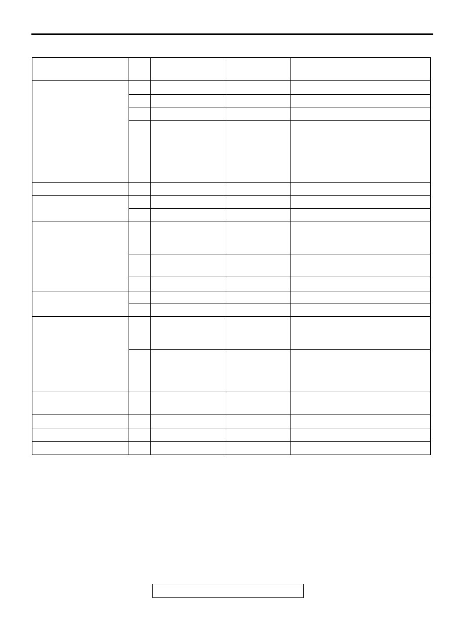
CENTRALIZED JUNCTION
TSB Revision
CIRCUIT DIAGRAMS
90-15
DEDICATED FUSE
POWER SUPPLY
CIRCUIT
NO. RATED
CAPACITY (A)
HOUSING
COLOR
CIRCUIT
Battery
1
−
−
−
2
15
Blue
Fog light
3
10
Red
Air conditioning system
4
10
Red
ECU power supply, dome light, trunk
light, universal garage door opener,
sunroof assembly, luggage
compartment light, audio system,
multi-center display, meter and
gauge
Ignition switch (ACC)
5
10
Red
Audio system
Headlight (High)
6
10
Red
Headlight and theft-alarm system
7
10
Red
Headlight and theft-alarm system
Taillight relay
8
10
Red
Rheostat, taillight, position light, rear
side marker light and illumination
circuit
9
10
Red
Taillight, position light, rear side
marker light and license plate light
10
−
−
−
Headlight relay (Low)
11
10
Red
Headlight
12
10
Red
Headlight
Battery
13
20
Yellow
INVECS-II 4A/T, MFI system, air
conditioning system, cooling system
and immobilizer system
14
10
Red
Charging system, central door
locking system <Vehicles with
keyless entry system>, turn-signal
light and hazard warning light
Fusible link No.4
15
20
Yellow
Audio system <Vehicles with
amplifier>
−
16
−
−
−
Fusible link No.4
17
20
Yellow
Sunroof <ECLIPSE>
Ignition switch (ACC)
18
20
Yellow
Windshield wiper and washer