Mitsubishi Eclipse / Eclipse Spyder (2000-2002). Service and repair manual - part 687


  Index      Mitsubishi     Mitsubishi Eclipse / Eclipse Spyder (2000-2002). Service and repair manual


Search            


Content   ..  685  686  687  688   ..


Mitsubishi Eclipse / Eclipse Spyder (2000-2002). Service and repair manual - part 687


AIR BAG MODULE(S) AND CLOCK SPRING

TSB Revision

SUPPLEMENTAL RESTRAINT SYSTEM (SRS)

52B-75

FRONT SEATBACK ASSEMBLY WITH SIDE AIR BAG 
MODULE CHECK

WARNING

If any improper part is found during the following 
inspection, replace the front seatback assembly 
with a new one. Dispose of the old one according 
to the specified procedure. (Refer to 

P.52B-80

.)

Never attempt to measure the circuit resistance of 
the air bag module (squib) even if you are using 
the specified tester. If the circuit resistance is 
measured with a tester, accidental air bag 
deployment will result in serious personal injury.

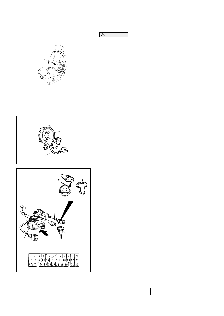
1. Check the air bag module deployment section for dents or 

deformation.

2. Check connector for damage, terminals for deformation, and 

harness for binds.

CLOCK SPRING CHECK
If any malfunction is found in steps 1 through 4, replace the 
clock spring with a new one.
1. Check the connectors and protective tube for damage, and 

the terminals for deformation.

2. Visually check the case for damage.

3. Align the paint mark of special tool MB991613 connector 

number 4 with the notch in clock spring connector number 2 
(arrow in the illustration) to connect the connectors number 
2 and 4.

4. Measure the resistance between the terminals 22 and 23 of 

special tool MB991613 connector number 5.

Standard value: less than 0.4 

AC002988AB

AIR BAG MODULE
DEPLOYMENT
SECTION

AC000390AB

CASE

PROTECTIVE TUBE

AC000400AB

MB991613

PAINT
MARK

5

4

A

VIEW A

(CLOCK SPRING
CONNECTOR 2)

SIDE IMPACT SENSOR

TSB Revision

SUPPLEMENTAL RESTRAINT SYSTEM (SRS)

52B-76

SIDE IM PA C T SENSO R

REMOVAL AND INSTALLATION

M1524004600050

A side impact sensor is installed behind the center pillar trim on both driver and passenger sides of the 
vehicle.

WARNING

Never attempt to disassemble or repair the side impact sensor. If faulty, replace it. 

Do not drop or subject the side impact sensor to impact or vibration. Replace the side 
impact sensor, if dents, cracking, deformation, or rust are present. 

Replace the side impact sensor after the air bag has deployed. 

SIDE IMPACT SENSOR

TSB Revision

SUPPLEMENTAL RESTRAINT SYSTEM (SRS)

52B-77

REMOVAL AND INSTALLATION

Pre-removal Operation

Turn the ignition key to "LOCK" (OFF) position.

Rear Seat Cushion Removal (Refer to GROUP 52A, Rear 
Seat 

P.52A-23

.)

Rear Seat Belt Removal (Refer to Rear Seat Bel

P.52A-

30

.)

Quarter Trim, Lower Removal (Refer to GROUP 52A, 
Trims 

P.52A-10

.)

Post-installation Operation

Quarter Trim, Lower Installation (Refer to GROUP 52A, 
Trims 

P.52A-10

.)

Rear Seat Belt Installation (Refer to Rear Seat Belt 

P.52A-30

.)

Rear Seat Cushion Installation (Refer to GROUP 52A, 
Rear Seat 

P.52A-23

.)

AC003133AB

<ECLIPSE>

<ECLIPSE SPYDER>

1

2

3

3

4.9 ± 1.0 N·m
44 ± 8 in-lb

4.9 ± 1.0 N·m
44 ± 8 in-lb

4.9 ± 1.0 N·m
44 ± 8 in-lb

4.9 ± 1.0 N·m
44 ± 8 in-lb

FRONT
SEAT BELT

FRONT OF
VEHICLE

REAR SPEAKER

QUATER PANEL,
LOWER

FRONT SEAT BELT

REAR SPEAKER
BRACKET

SIDE IMPACT SENSOR

TSB Revision

SUPPLEMENTAL RESTRAINT SYSTEM (SRS)

52B-78

NOTE: The illustration above shows the side impact 
sensor (RH). The position of the side impact sensor 
(LH) is symmetrical to this.

REMOVAL SERVICE POINT

<<A>> NEGATIVE (

) BATTERY CABLE DISCONNECTION

DANGER

Wait at least 60 seconds after disconnecting the 
battery cable before doing any further work. (Refer to 

P.52B-15

.)

WARNING

Battery posts, terminals and related accessories 
contain lead and lead compounds. WASH HANDS 
AFTER HANDLING.

Disconnect the negative (

) battery cable from the battery and 

tape the terminal to prevent accidental connection and air bag 
deployment.

INSTALLATION SERVICE POINTS

>>A<< PRE-INSTALLATION INSPECTION
Check the side impact sensor for dents, breakage and bending 
and measure the resistance between the terminals, even when 
installing a new side impact sensor.

REMOVAL STEPS

<<A>>

1.

NEGATIVE (-) BATTERY CABLE 
CONNECTION

2.

SIDE IMPACT SENSOR BRACKET

3.

SIDE IMPACT SENSOR

INSTALLATION STEPS

>>A<<

PRE-INSTALLATION INSPECTION

>>B<<

3.

SIDE IMPACT SENSOR

2.

SIDE IMPACT SENSOR BRACKET

1.

NEGATIVE (-) BATTERY CABLE 
CONNECTOR

>>C<<

POST-INSTALLATION 
INSPECTION

ACX00583

INSULATING TAPE

BATTERY

BATTERY CABLE (–)

AC


Content   ..  685  686  687  688   ..