Mitsubishi Eclipse / Eclipse Spyder (2000-2002). Service and repair manual - part 685
SRS CONTROL UNIT (SRS-ECU)
TSB Revision
SUPPLEMENTAL RESTRAINT SYSTEM (SRS)
52B-67
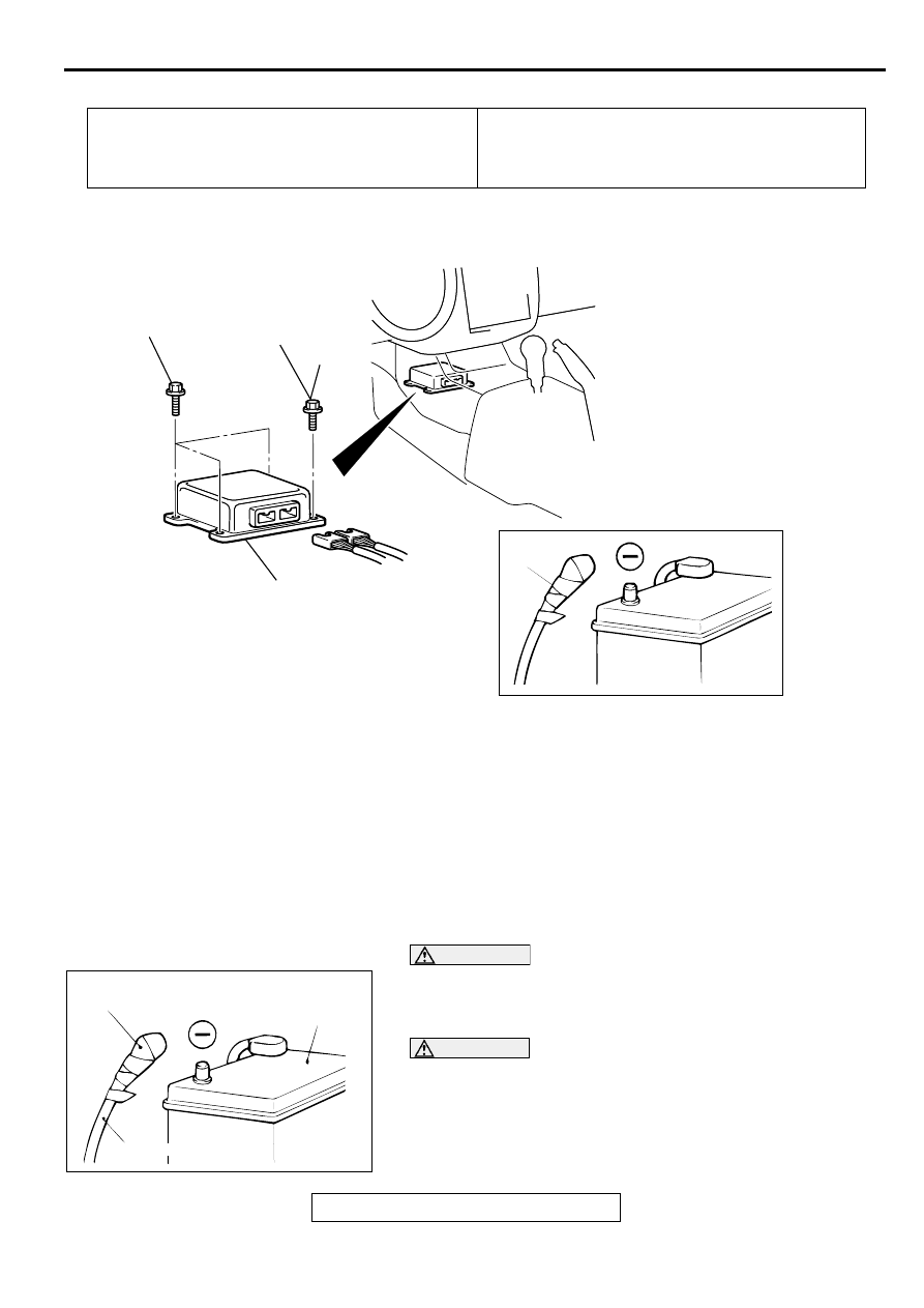
REMOVAL AND INSTALLATION
REMOVAL SERVICE POINT
<<A>> NEGATIVE (-) BATTERY CABLE DISCONNECTION
DANGER
Wait at least 60 seconds after disconnecting the
battery cable before doing any further work. (Refer to
.)
WARNING
Battery posts, terminals and related accessories
contain lead and lead compounds. WASH HANDS
AFTER HANDLING.
Disconnect the negative battery cable from the battery and
tape the terminal to prevent accidental connection and
deployment.
Pre-removal Operation
•
Turn the ignition switch to "LOCK" (OFF) position.
•
Floor Console Removal (Refer to GROUP 52A, Floor
Console
Post-installation Operation
•
Floor Console Installation (Refer to GROUP 52A, Floor
Console
.)
AC003160AB
1
2
3
4.9 ± 1.0 N·m
44 ± 8 in-lb
4.9 ± 1.0 N·m
44 ± 8 in-lb
REMOVAL STEPS
<<A>>
1.
NEGATIVE (-) BATTERY CABLE
CONNECTION
2.
BRACKET MOUNTING BOLT
(GROUNDING BOLT)
3.
SRS-ECU
INSTALLATION STEPS
>>A<<
3.
SRS-ECU
>>B<<
2.
BRACKET MOUNTING BOLT
(GROUNDING BOLT)
1.
NEGATIVE (-) BATTERY CABLE
CONNECTION
>>C<<
•
POST-INSTALLATION
INSPECTION
ACX00583
INSULATING TAPE
BATTERY
BATTERY CABLE (–)
AC