Mitsubishi Eclipse / Eclipse Spyder (2000-2002). Service and repair manual - part 680
 

  Index      Mitsubishi     Mitsubishi Eclipse / Eclipse Spyder (2000-2002). Service and repair manual


Search            


Content   ..  678  679  680  681   ..


Mitsubishi Eclipse / Eclipse Spyder (2000-2002). Service and repair manual - part 680


SRS AIR BAG DIAGNOSIS

TSB Revision

SUPPLEMENTAL RESTRAINT SYSTEM (SRS)

52B-47

STEP 2. Check the harness wires between SRS-ECU 
connector C-74 and side impact sensor (RH) connector D-
02.
Q: Are the harness wires between SRS-ECU connector C-

74 and side impact sensor (RH) connector D-02? 
YES : 
Go to Step 3.
NO :  Repair them. Then go to Step 3.

STEP 3. Check for DTC.

Q: Is any of DTC 89 or 96 output?

YES : Replace the SRS-ECU. Refer to 

P.52B-66

.

NO :  This diagnosis is compleate.(If no malfunctions are 

not found in all steps, an intermittent malfunction is 
suspected. Refer to GROUP 00, How to Use 
Troubleshooting/Inspection Service Points 

−

 How to 

Cope with Intermittent Malfunction 

P.00-6

.)      

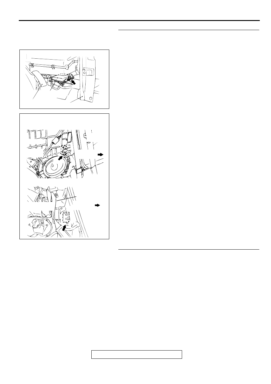
AC000358AF

CONNECTOR: C-74

SRS-ECU

ACCELERATOR PEDAL

CENTER REINFORCEMENT (LH)

AC003136AB

CONNECTOR: D-02

<ECLIPSE>

<ECLIPSE SPYDER>

FRONT
SEAT BELT

FRONT OF
VEHICLE

REAR
SPEAKER

FRONT
SEAT BELT

FRONT OF
VEHICLE

REAR SPEAKER
BRACKET

SRS AIR BAG DIAGNOSIS

TSB Revision

SUPPLEMENTAL RESTRAINT SYSTEM (SRS)

52B-48

DTC 91: Left hand side-impact sensor power supply circuit system

AC003886AC

Side Impact Sensor (LH) Power Supply Circuit

AC000358AF

CONNECTOR: C-74

SRS-ECU

ACCELERATOR PEDAL

CENTER REINFORCEMENT (LH)

SRS AIR BAG DIAGNOSIS

TSB Revision

SUPPLEMENTAL RESTRAINT SYSTEM (SRS)

52B-49

CIRCUIT OPERATION

•

The SRS-ECU judges how severe a collision is 
by detecting signals from the side impact sensor 
and the analog G-sensor. If the impact is over a 
predetermined level, the SRS-ECU outputs an 
ignition signal. At this time, if the safing G-sensor 
is on, the SRS air bag will inflate.

DTC SET CONDITIONS

•

This DTC is output if a poor connection at the 
SRS-ECU is detected. However, if the vehicle 
condition returns to normal, DTC number 34 will 
be automatically erased, and the SRS warning 
light will go out.

TROUBLESHOOTING HINTS

•

Damaged connectors

•

Malfunction of the side air bag module (LH) 
(squib)

•

Malfunction of the SRS-ECU

DIAGNOSIS

Required Special Tools:

•

MB991502: Scan Tool (MUT-II)

AC003136AB

CONNECTOR: D-12

<ECLIPSE>

<ECLIPSE SPYDER>

FRONT
SEAT BELT

FRONT OF
VEHICLE

REAR
SPEAKER

FRONT
SEAT BELT

FRONT OF
VEHICLE

REAR SPEAKER
BRACKET

SRS AIR BAG DIAGNOSIS

TSB Revision

SUPPLEMENTAL RESTRAINT SYSTEM (SRS)

52B-50

STEP 1. Check the side impact sensor (LH) line at the SRS-
ECU connector C-74 by backprobing.
(1) Do disconnect the side impact sensor (LH) connector D-12.
(2) Connect the negative battery terminal.
(3) Turn the ignition switch to "ON" position.
(4) Measure the voltage between terminal 4 and the ground by 

backprobing.

•

Voltage should be 9 volts or more

(5) Check the continuity between terminal 1 and the ground by 

backprobing.

•

Should be less than 2 ohm.

Q:  Does the voltage meet the specifications or is the 

resistance less than 2 ohm?
YES : 
Replace the side impact sensor (LH). Refer to 

P.52B-

76

. Then go to Step 3.

NO :  Go to Step 2.

ACX01658

1 2 3 4

AD

D-12 CONNECTOR
HARNESS SIDE VIEW

ACX01659

1 2 3 4

AD

D-12 CONNECTOR
HARNESS SIDE VIEW


Content   ..  678  679  680  681   ..