Mitsubishi Eclipse / Eclipse Spyder (2000-2002). Service and repair manual - part 672
TSB Revision
SUPPLEMENTAL RESTRAINT SYSTEM (SRS)
52B-15
M1524000300079
WARNING
•
In order to avoid injury to yourself or others from
accidental deployment of the air bag during
servicing, read and carefully follow all the
precautions and procedures described in this
manual.
•
After disconnecting the battery cable, wait 60
seconds or more before proceeding with the
following work. The SRS system is designed to
retain enough voltage to deploy the air bag for a
short time even after the battery has been
disconnected, so serious injury may result from
unintended air bag deployment if work is done on
the SRS system immediately after the battery
cables are disconnected.
•
Battery posts, terminals and related accessories
contain lead and lead compounds. WASH HANDS
AFTER HANDLING.
•
Do not use any electrical test equipment on or near
the SRS components, except those specified on
•
Never Attempt to Repair the Following
Components: SRS-ECU, Clock Spring, Air Bag
Module, Side Impact Sensor. If any of these
components are diagnosed as faulty, they should
only be replaced, in accordance with the
INDIVIDUAL COMPONENT SERVICE procedures in
this manual, starting on page
•
Do not attempt to repair the wiring harness
connectors of the SRS. If any of the connectors are
diagnosed as faulty, replace the wiring harness. If
the wires are diagnosed as faulty, replace or repair
the wiring harness according to the following
table.
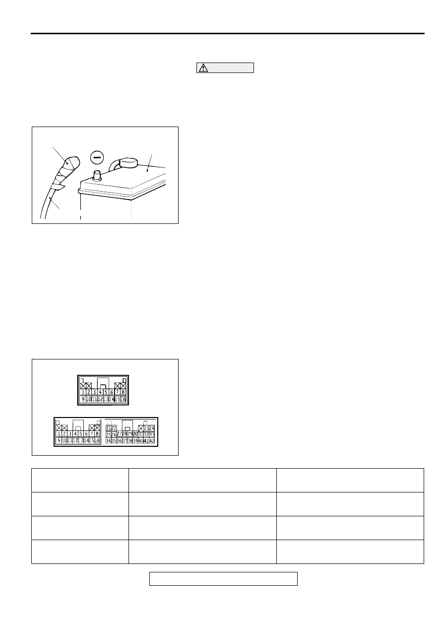
ACX00583
INSULATING TAPE
BATTERY
BATTERY CABLE (–)
AC
AC002967AB
SRS-ECU CONNECTOR
<VEHICLES WITHOUT SRS SIDE AIR BAG>
<VEHICLES WITH SRS SIDE AIR BAG>
SRS-ECU TERMINAL
NO.
DESTINATION OF HARNESS
CORRECTIVE ACTION
3
Body wiring harness
→
Ground
Correct or replace the body wiring
harness.
4
Body wiring harness
→
Instrument
panel wiring
→
SRS warning light
Correct or replace each wiring harness.
5, 6
Body wiring harness
→
Air bag module
(Front passenger's side)
Correct or replace the body wiring
harness.