Mitsubishi Eclipse / Eclipse Spyder (2000-2002). Service and repair manual - part 594
TRACTION CONTROL SYSTEM (TCL) DIAGNOSIS
TSB Revision
TRACTION CONTROL SYSTEM (TCL)
35C-11
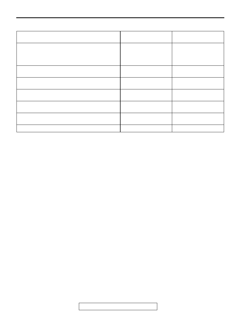
SYMPTOM CHART
M1354000700043
SYMPTOMS
INSPECTION
PROCEDURE NO.
REFERENCE PAGE
Communication between the scan tool and all
systems is not possible.
−
GROUP 13A, Diagnosis
or GROUP
13B, Diagnosis
Communication between the scan tool and the ABS-
ECU is not possible.
1
When the ignition key is turned to "ON" (engine
stopped), the TCL indicator light does not illuminate.
2
When the ignition key is turned to "ON" (engine
stopped), the TCL warning light does not illuminate.
3
The TCL indicator light remains illuminated after the
engine is started.
4
The TCL warning light remains illuminated after the
engine is started.
5
The TCL system does not operate.
6