Mitsubishi Eclipse / Eclipse Spyder (2000-2002). Service and repair manual - part 588


  Index      Mitsubishi     Mitsubishi Eclipse / Eclipse Spyder (2000-2002). Service and repair manual


Search            


Content   ..  586  587  588  589   ..


Mitsubishi Eclipse / Eclipse Spyder (2000-2002). Service and repair manual - part 588


ANTI-SKID BRAKING SYSTEM (ABS) DIAGNOSIS

TSB Revision

ANTI-LOCK BRAKING SYSTEM (ABS)

35B-43

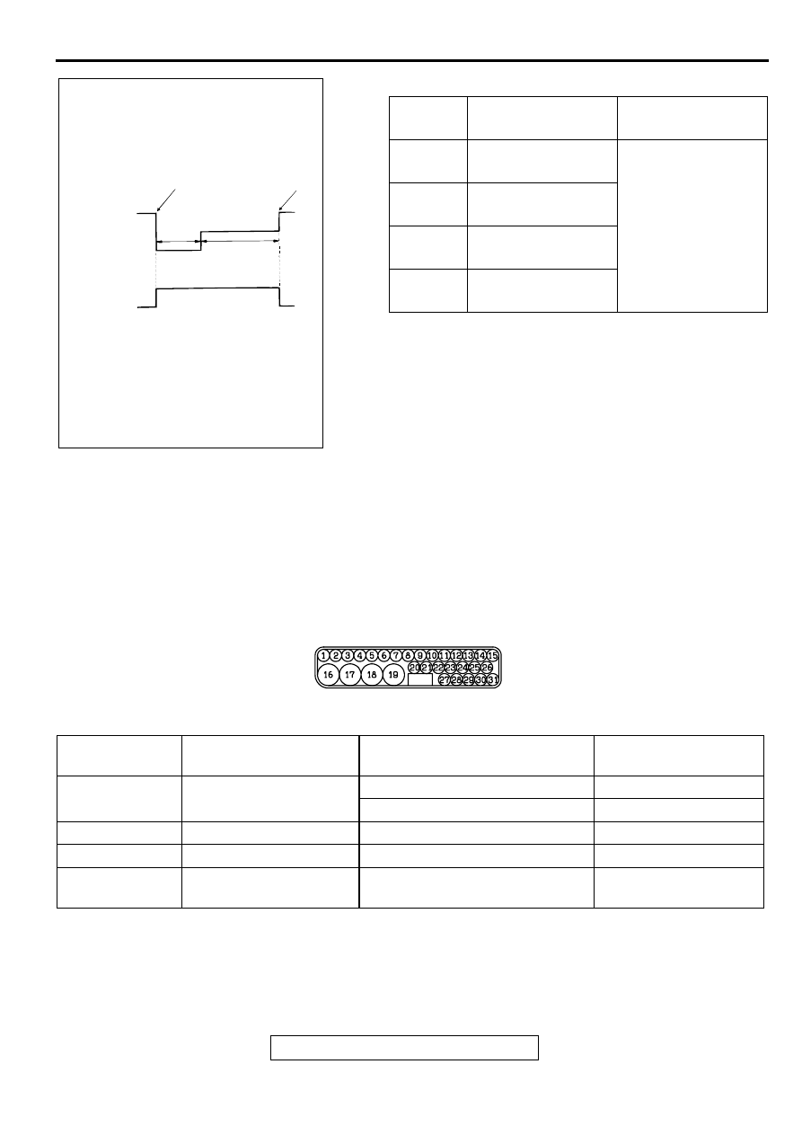
ACTUATOR TEST SPECIFICATIONS

CHECK AT ABS-ECU

M1352011800093

TERMINAL VOLTAGE CHECK CHART
1. Measure the voltages between terminals (16) and 

(19) (ground terminals) and each respective 
terminal.

2. The terminal layouts are shown in the illustrations 

below.

NOTE: Do not measure terminal voltage for 
approximately three seconds after the ignition switch 
is turned "ON." The ABS-ECU performs the initial 
check during that period.

RESISTANCE AND CONTINUITY BETWEEN 
HARNESS-SIDE CONNECTOR TERMINALS
1. Turn the ignition switch to the "LOCK" (OFF) 

position and disconnect the ABS-ECU connectors 
before checking resistance and continuity.

2. Check between the terminals indicated in the 

table below.

3. The terminal layouts are shown in the illustration 

below.

NO.

ITEM

PARTS TO BE 
ACTIVATED

01

Solenoid valve for 
front-left wheel

Solenoid valves and 
pump motors in the 
hydraulic unit (simple 
inspection mode)

02

Solenoid valve for 
front-right wheel

03

Solenoid valve for 
rear-left wheel

04

Solenoid valve for 
rear-right wheel

AC000971AC

ACTIVATION PATTERN

A

B

C

SOLENOID
VALVE

END OF
FORCED
ACTION

START OF
FORCED
ACTION

1 s

2 s

PUMP
MOTOR

ON

OFF

NOTE
A:
B:
C:

HYDRAULIC PRESSURE DECREASES
HYDRAULIC PRESSURE HOLDS
HYDRAULIC PRESSURE INCREASES

AC002089 AB

CONNECTOR 
TERMINAL NO

SIGNAL

CHECKING REQUIREMENT

NORMAL CONDITION

14

Input from stoplight 
switch

Stoplight switch: ON

Battery positive voltage

Stoplight switch: OFF

Approximately 0 V

15

ABS-ECU power supply

Ignition switch: "ON" 

Battery positive voltage

17

Motor power supply

Always

Battery positive voltage

18

Solenoid valve power 
supply

Always

Battery positive voltage

SPECIAL TOOLS

TSB Revision

ANTI-LOCK BRAKING SYSTEM (ABS)

35B-44

SPECIA L TO O LS

M1352000600073

AC002090 AB

CONNECTOR TERMINAL NO.

SIGNAL

NORMAL CONDITION

 7

Front-left wheel speed sensor

1.28 

 1.92 k

 3

Rear-right wheel speed sensor

1.28 

 1.92 k

 5

Front-right wheel speed sensor

1.28 

 1.92 k

 9

Rear-left wheel speed sensor

1.28 

 1.92 k

16 

 body ground

Solenoid valve ground

Less than 2 ohms

TOOL

TOOL NUMBER AND 
NAME

SUPERSESSION

APPLICATION

MB991502
Scan tool (MUT-II)

MB991496-OD

For checking of ABS 
(Diagnostic trouble code 
display when using the 
scan tool)

MB991529
Diagnostic trouble code 
check harness

Tool not necessary if scan 
tool (MUT-II) is available.

For checking of ABS 
(Diagnostic trouble code 
display when using the 
ABS warning light)

MB991223 
Harness set
 A:MB991219
 Inspection harness
 B:MB991220
 LED harness
 C:MB991221
 LED harness adaptor
 D:MB991222
 Probe

MB991223
MB991709-01

Making voltage and 
resistance measurement 
during troubleshooting
A: Connector pin contact
B: Power circuit 
inspection
C: Power circuit 
inspection
D: Commercial tester 
connection

B991502

MB991529

MB991223

A

AB

B

C

D

ON-VEHICLE SERVICE

TSB Revision

ANTI-LOCK BRAKING SYSTEM (ABS)

35B-45

O N -VEH IC LE SERVIC E

BLEEDING

M1352001500057

CAUTION

Use the specified brake fluid. Avoid using a mixture of the 
specified brake fluid and other fluid. 

Specified brake fluid: Conforming to DOT 3 or DOT 4

MASTER CYLINDER BLEEDING

Refer to GROUP 35A 

 On-vehicle Service 

 Bleeding 

P.35A-

22

.

BRAKE LINE BLEEDING

CAUTION

Be sure to filter/strain the brake fluid being added to the 
master cylinder reservoir tank. Debris may damage the 
hydraulic unit.
Refer to GROUP 35A 

 On-vehicle Service 

 Bleeding 

P.35A-

22

.

WHEEL SPEED SENSOR OUTPUT VOLTAGE 
MEASUREMENT

M1352001600076

Required Special Tool:
MB991219: Inspection Harness
1. Lift up the vehicle and release the parking brake.

2. Disconnect the ABS-ECU connector, and then use special 

tool MB991219 to measure the output voltage at the 
harness side connector.

3. Manually turn the wheel to be measured 1/2 to 1 turn/

second. Measure the output voltage with a voltmeter or 
oscilloscope.

Output voltage:

Minimal voltmeter reading: 42 mV

Maximum voltmeter reading: 300 mV

Minimal oscilloscope reading: 120 mV

Maximum oscilloscope reading: 600 mV

Probable causes of low output voltage

Wheel speed sensor pole piece-to-ABS rotor clearance too 
large

Faulty wheel speed sensor

TERMINAL NO.

Front left

Rear right

Front right

Front left

6

1

4

8

7

3

5

9

AC000948 AB

ABS-ECU CONNECTOR
(HARNESS SIDE)

ON-VEHICLE SERVICE

TSB Revision

ANTI-LOCK BRAKING SYSTEM (ABS)

35B-46

NOTE: Check the connection of the sensor harness and 
connector before using the oscilloscope.
4. To observe the waveform with an oscilloscope:

Front Wheels: Shift into low gear and drive the wheels.

Rear Wheels: Turn the wheels manually at a constant 
speed

NOTE: The output waveform is low when the wheel speed is 
low. Similarly, it will be higher as the wheel speed increases. 
Waveform may also be observed by driving the vehicle.

POINTS IN WAVEFORM MEASUREMENT

NOTE: The wheel speed sensor cable moves in relation to motion of the front or rear suspension. Therefore, 
it is likely that it has an open circuit only when driving on rough roads but it functions normally when driving on 
smooth roads. It is recommended to observe sensor output voltage waveform also under special conditions, 
such as driving on a rough road.

AC000949 AB

WHEN TURNED MANUALLY

IN LOW GEAR, IDLING
[5 

 6 km/h (3 

 4 mph)]

[10.0 ms/DIV 1 V/DIV]

[10.0 ms/DIV 1 V/DIV]

SYMPTOM

PROBABLE CAUSES

REMEDY

Too small or zero waveform 
amplitude

Faulty wheel speed sensor

Replace sensor

Incorrect pole piece-to-ABS rotor 
clearance

Adjust clearance

Waveform amplitude fluctuates 
excessively (This is no problem if 
the minimum amplitude is 100 mV 
or more)

Axle hub eccentric or with large 
runout

Replace hub

Noisy or disturbed waveform

Open circuit in wheel speed sensor Replace sensor

Open circuit in harness

Repair harness

Incorrectly mounted wheel speed 
sensor

Mount correctly

ABS rotor with missing or 
damaged teeth

Replace ABS rotor


Content   ..  586  587  588  589   ..