Mitsubishi Eclipse / Eclipse Spyder (2000-2002). Service and repair manual - part 586


  Index      Mitsubishi     Mitsubishi Eclipse / Eclipse Spyder (2000-2002). Service and repair manual


Search            


Content   ..  584  585  586  587   ..


Mitsubishi Eclipse / Eclipse Spyder (2000-2002). Service and repair manual - part 586


ANTI-SKID BRAKING SYSTEM (ABS) DIAGNOSIS

TSB Revision

ANTI-LOCK BRAKING SYSTEM (ABS)

35B-35

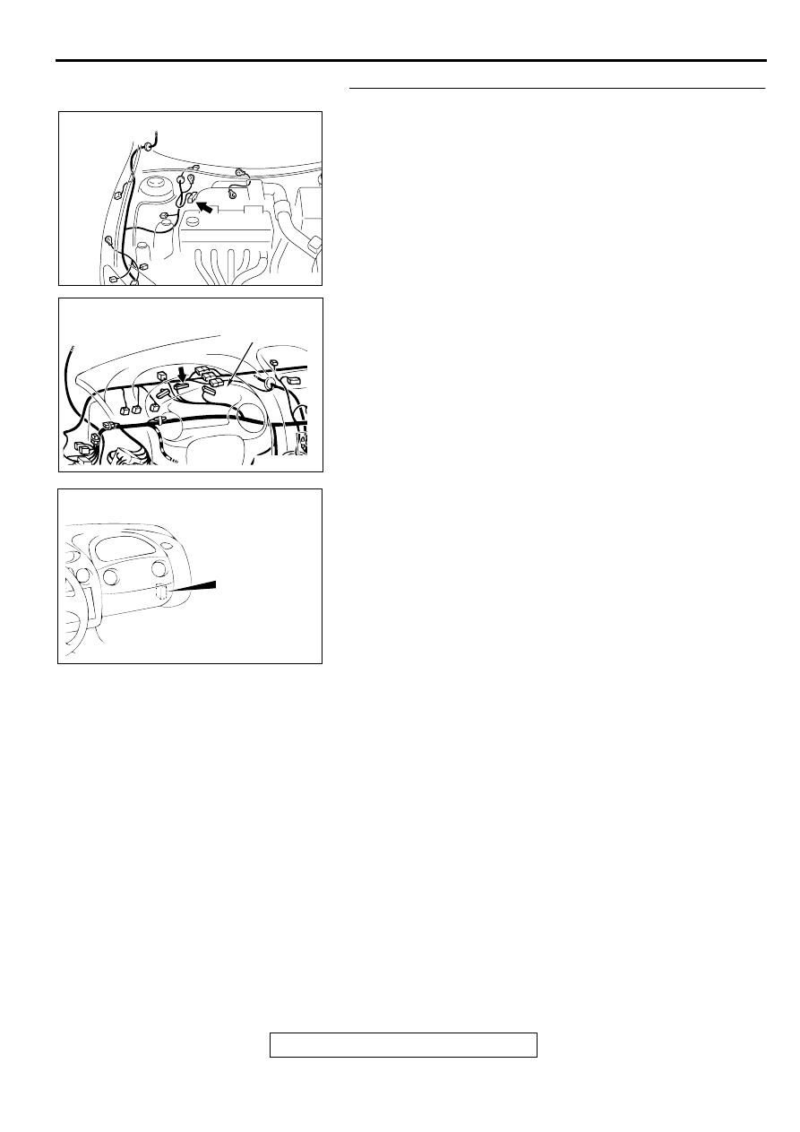
STEP 5. Check the connectors A-02, C-42, and C-94.
Refer to GROUP 00E, Harness Connector Inspection 

P.00E-2

.

Q: Is any of the connectors damaged?

YES : Repair it and then go to Step 9.
NO :  Go to Step 6.

AC001985

CONNECTOR: A-02

AD

AC004483AB

CONNECTOR: C-42

COMBINATION 
METER

AC004410AB

CONNECTOR: C-94

ANTI-SKID BRAKING SYSTEM (ABS) DIAGNOSIS

TSB Revision

ANTI-LOCK BRAKING SYSTEM (ABS)

35B-36

STEP 6. Check the continuity between the combination 
meter and the ABS-ECU.
Check the continuity between the combination meter connector 
C-42 (terminal 24) and the ABS-ECU connector A-02 (terminal 
21).

NOTE: This check must be done with the ABS-ECU connector 
A-02 is connected to the ABS-ECU. Disconnection of the ABS-
ECU connector A-02 makes the connector lock switch OFF, so 
this continuity check could not be done.

Q: Is there the continuity between the combination meter 

connector C-42 (terminal 24) and the ABS-ECU 
connector A-02 (terminal 21)?
YES : 
Go to Step 9.
NO :  Repair the harness wire and then go to Step 9.

STEP 7. Check the connectors C-41, C-101, and C-104.
Refer to GROUP 00E, Harness Connector Inspection 

P.00E-2

.

Q: Is any of the connectors damaged?

YES : Repair it and then go to Step 9.
NO :  Go to Step 8.

AC001985

CONNECTOR: A-02

AD

AC004483AB

CONNECTOR: C-42

COMBINATION 
METER

AC004482 AB

CONNECTOR: C-41

COMBINATION METER

AC004411AB

CONNECTORS: C-101, C-104

C-104

C-101

ANTI-SKID BRAKING SYSTEM (ABS) DIAGNOSIS

TSB Revision

ANTI-LOCK BRAKING SYSTEM (ABS)

35B-37

STEP 8. Check the continuity between the ignition switch 
(IG1) and the combination meter.
Q: Is there any continuity (less than 2 ohm) between the 

ignition switch (IG1) and the combination meter 
connector C-41 (terminal 52)?
YES : 
Go to Step 9.
NO :  Repair the harness wire and then go to Step 9.

STEP 9. Check symptoms.

Q: Does the ABS warning light illuminate for 3 seconds 

when the ignition switch is turned to the "ON" position 
with engine stopped or upon start-up?
YES : 
This diagnosis is complete.
NO :  Return to Step 1.

AC004482 AB

CONNECTOR: C-41

COMBINATION METER

ANTI-SKID BRAKING SYSTEM (ABS) DIAGNOSIS

TSB Revision

ANTI-LOCK BRAKING SYSTEM (ABS)

35B-38

INSPECTION PROCEDURE 3: The ABS Warning Light Remains Illuminated after the Engine is Started.

NOTE: This diagnosis procedure is limited to cases where communication with the scan tool is possible 
(ABS-ECU power supply is normal) and no diagnostic trouble code outputs.

NOTE: CONNECTOR LOCK SWITCH
ON: The ABS-ECU connector A-02 is connected.

OFF: The ABS-ECU connector A-02 is disconnected.

ABS Warning Light Circuit


Content   ..  584  585  586  587   ..