Mitsubishi Eclipse / Eclipse Spyder (2000-2002). Service and repair manual - part 587
ANTI-SKID BRAKING SYSTEM (ABS) DIAGNOSIS
TSB Revision
ANTI-LOCK BRAKING SYSTEM (ABS)
35B-39
CIRCUIT OPERATION
•
The ABS-ECU controls the illumination of the
ABS warning light by turning the power transistor
in the control unit ON and OFF.
•
The ABS-ECU illuminates the ABS warning light
on start-up. It turns the light off after 3 seconds
when the ABS-ECU completes the self-check.
•
When the ABS-ECU connector is disconnected,
the circuit is grounded to illuminate the light by
the connector lock switch OFF operation.
TECHNICAL DESCRIPTION (COMMENT)
The cause is probably the ABS-ECU malfunction.
TROUBLESHOOTING HINTS (The most likely
causes for this condition:)
•
Malfunction of the ABS-ECU connector lock
•
Disconnection of the ABS-ECU connector
•
Damaged wiring harness or connector
•
Malfunction of the hydraulic unit (integrated with
ABS-ECU)
DIAGNOSIS
Confirm the ABS-ECU connector connection and locking. If the
connector is connected and locked to the ABS-ECU correctly,
perform the following diagnosis.
Required Special Tool:
•
MB991223: Harness Set
STEP 1. Check the ABS warning light circuit at the
intermediate connector C-94.
(1)Disconnect the intermediate connector C-94.
(2)Turn the ignition switch to the "ON" position.
Q: Does the ABS warning light illuminate?
YES : Go to Step 4.
NO : Go to Step 2.
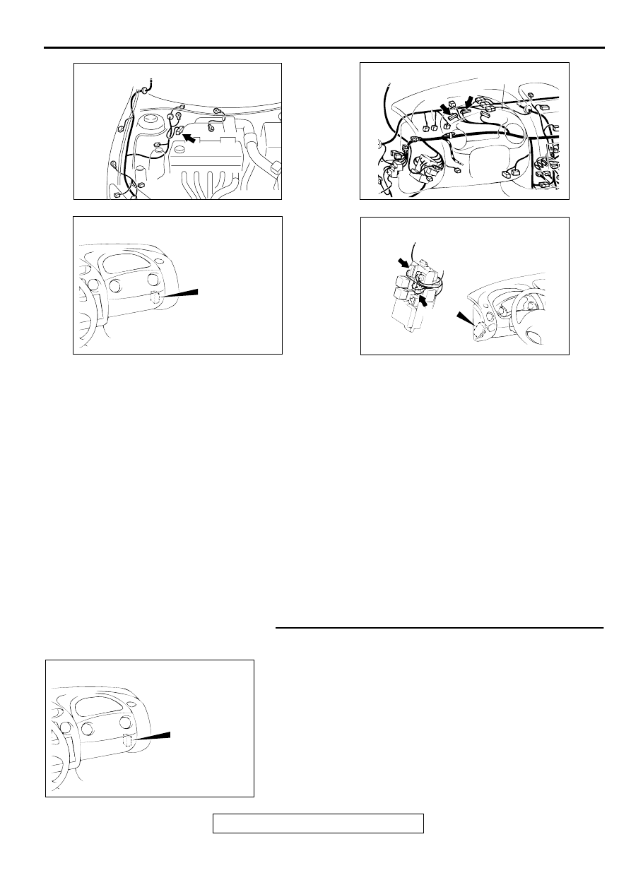
AC001985
CONNECTOR: A-02
AD
AC004428 AB
CONNECTORS: C-41, C-42
C-41
C-42
COMBINATION
METER
AC004410AB
CONNECTOR: C-94
AC004411AB
CONNECTORS: C-101, C-104
C-104
C-101
AC004410AB
CONNECTOR: C-94