Mitsubishi Eclipse / Eclipse Spyder (2000-2002). Service and repair manual - part 584
 

  Index      Mitsubishi     Mitsubishi Eclipse / Eclipse Spyder (2000-2002). Service and repair manual


Search            


Content   ..  582  583  584  585   ..


Mitsubishi Eclipse / Eclipse Spyder (2000-2002). Service and repair manual - part 584


ANTI-SKID BRAKING SYSTEM (ABS) DIAGNOSIS

TSB Revision

ANTI-LOCK BRAKING SYSTEM (ABS)

35B-27

SYMPTOM PROCEDURES

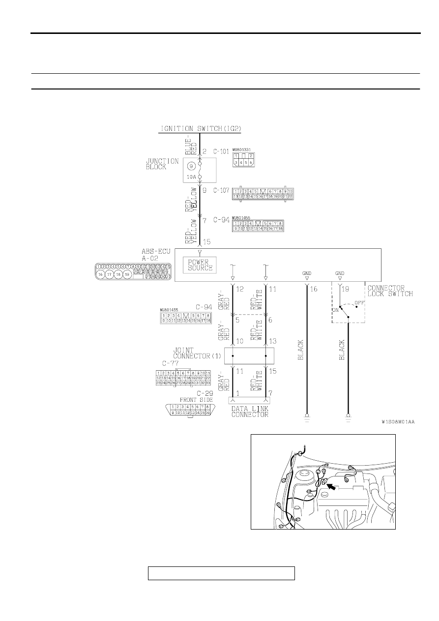
INSPECTION PROCEDURE 1: Communication between the Scan Tool and ABS-ECU Is not Possible. 

NOTE: CONNECTOR LOCK SWITCH
ON: The ABS-ECU connector A-02 is connected.
OFF: The ABS-ECU connector A-02 is disconnected.

Data Link Connector Circuit

AC001985

CONNECTOR: A-02

AD

ANTI-SKID BRAKING SYSTEM (ABS) DIAGNOSIS

TSB Revision

ANTI-LOCK BRAKING SYSTEM (ABS)

35B-28

CIRCUIT OPERATION

•

The diagnostic output is made from the ABS-
ECU (terminal 11) to the diagnostic output 
terminal (terminal 7) of the data link connector.

•

When the data link connector's diagnostic test 
mode control terminal (terminal 1) is grounded, 
the ABS-ECU (terminal 12) will go into diagnostic 
mode.

TECHNICAL DESCRIPTION (COMMENT)
When communication with the scan tool is not 
possible, the cause is probably an open circuit in the 
ABS-ECU power circuit or an open circuit in the 
diagnostic output circuit.

TROUBLESHOOTING HINTS (The most likely 
causes for this case:)

•

Blown fuse

•

Damaged wiring harness or connector

•

Malfunction of the hydraulic unit (Integrated with 
ABS-ECU)

DIAGNOSIS

Required Special Tool:

•

MB991223: Harness Set

AC004429AB

CONNECTOR: C-29

COMBINATION METER

AC004427AB

CONNECTOR: C-77

COMBINATION 
METER

AC004410AB

CONNECTOR: C-94

AC004413AB

CONNECTORS: C-101, C-107

C-107

C-101

ANTI-SKID BRAKING SYSTEM (ABS) DIAGNOSIS

TSB Revision

ANTI-LOCK BRAKING SYSTEM (ABS)

35B-29

STEP 1. Check the power supply circuit at the ABS-ECU 
connector A-02.
(1)Disconnect the ABS-ECU connector A-02 and measure at 

the harness side.

(2)Start the engine.
(3)Measure the voltage between terminal 15 and ground.

Q: Is the voltage approximately 12 volts (battery positive 

voltage)? 
YES : 
Go to Step 3.
NO :  Go to Step 2.

STEP 2. Check the harness wire between the ignition 
switch (IG2) and the ABS-ECU connector A-02.
NOTE: After inspecting the intermediate connector C-94, C-
101, or C-107, inspect the wire. If the intermediate connector 
C-94, C-101, or C-107 is damaged, repair or replace it. Refer to 
GROUP 00E, Harness Connector Inspection 

P.00E-2

. If the 

connector has been repaired or replaced, go to Step 3 .

Q: Is the harness wire between the ignition switch (IG2) 

and the ABS-ECU connector A-02 damaged?
YES : 
Repair it and go to Step 5.
NO :  Go to Step 3.

AC000947

A-02 (HARNESS SIDE)

AB

AC001985

CONNECTOR: A-02

AD

AC004410AB

CONNECTOR: C-94

AC004413AB

CONNECTORS: C-101, C-107

C-107

C-101

ANTI-SKID BRAKING SYSTEM (ABS) DIAGNOSIS

TSB Revision

ANTI-LOCK BRAKING SYSTEM (ABS)

35B-30

STEP 3. Check the harness wires between the ABS-ECU 
connector A-02 and the data link connector C-29.
NOTE: After inspecting the intermediate connector C-77 or C-
94, inspect the wires. If the intermediate connector C-77 or C-
94 is damaged, repair or replace it. Refer to GROUP 00E, 
Harness Connector Inspection 

P.00E-2

. If the connector has 

been repaired or replaced, go to Step 4.

Q: Is any of the harness wires between the ABS-ECU 

connector A-02 and the data link connector C-29 
damaged?
YES : 
Repair it and go to Step 5.
NO :  Go to Step 4.

AC001985

CONNECTOR: A-02

AD

AC004429AB

CONNECTOR: C-29

COMBINATION METER

AC004427AB

CONNECTOR: C-77

COMBINATION 
METER

AC004410AB

CONNECTOR: C-94


Content   ..  582  583  584  585   ..