Mitsubishi Eclipse / Eclipse Spyder (2000-2002). Service and repair manual - part 568


  Index      Mitsubishi     Mitsubishi Eclipse / Eclipse Spyder (2000-2002). Service and repair manual


Search            


Content   ..  566  567  568  569   ..


Mitsubishi Eclipse / Eclipse Spyder (2000-2002). Service and repair manual - part 568


ON-VEHICLE SERVICE

TSB Revision

BASIC BRAKE SYSTEM

35A-21

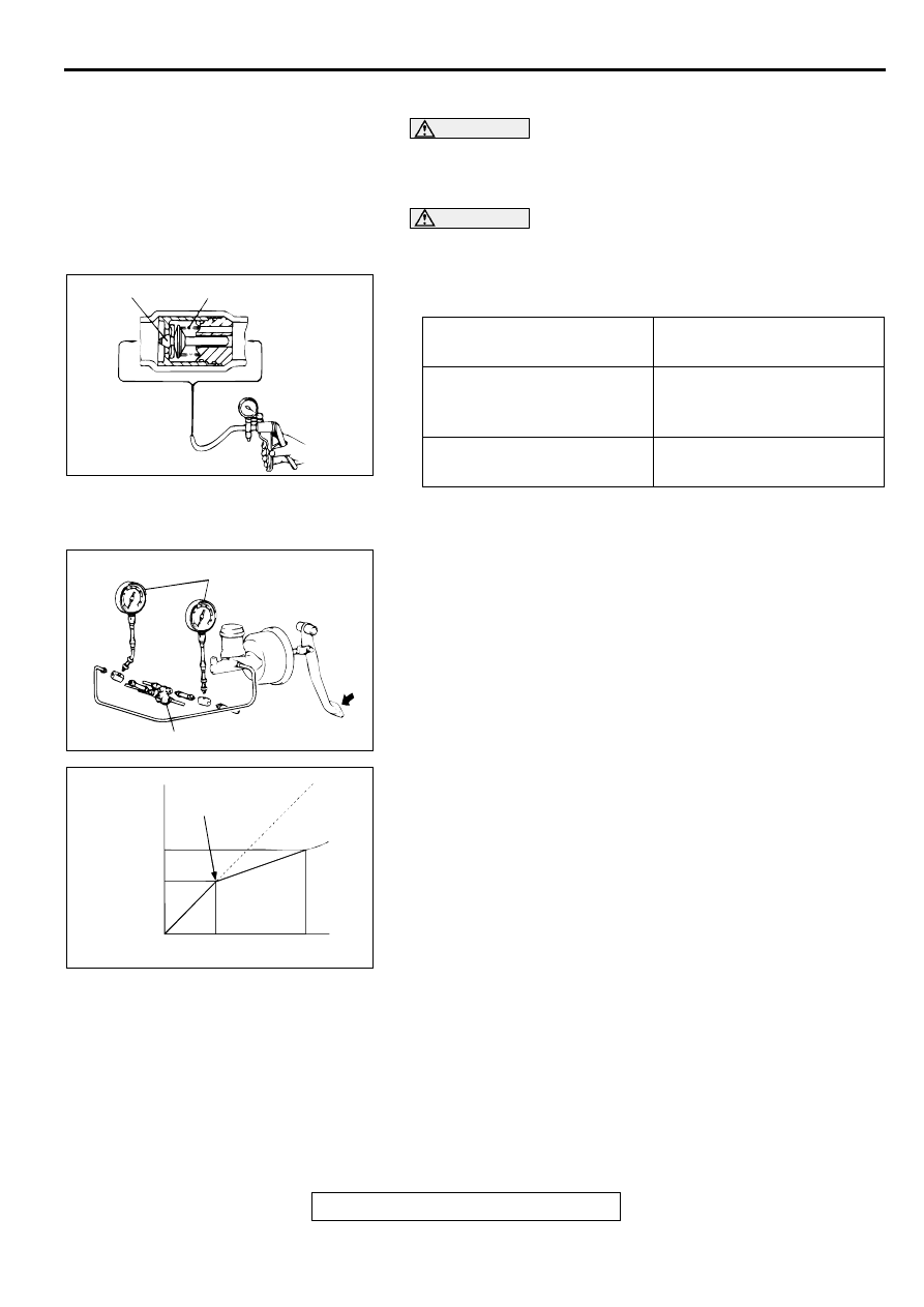
CHECK VALVE OPERATION CHECK

M1351009000075

CAUTION

The check valve should not be removed from the vacuum 
hose.
1. Remove the vacuum hose. (Refer to 

P.35A-32

.)

CAUTION

If the check valve is defective, replace it as an assembly 
unit together with the vacuum hose.
2. Check the operation of the check valve by using a vacuum 

pump.

PROPORTIONING VALVE FUNCTION TEST

M1351001100078

1. Connect two pressure gauges, one each to the input side 

and output side of the proportioning valve, as shown.

2. Air bleed the brake line and the pressure gauge.

3. While gradually depressing the brake pedal, make the 

following measurements and check to be sure that the 
measured values are within the allowable range.

(1) Output fluid pressure begins to drop relative to input fluid 

pressure (split point).

Standard value: 2.7 

 3.2 MPa (391 

 462 psi)

(2) Check that the output fluid pressure is at standard value 

when the input fluid pressure indicates 9.8 MPa (1,422 
psi).

Standard value: 4.3 

 5.1 MPa (619 

 732 psi)

(3) Output fluid pressure difference between left and right 

brake lines.

Limit: 0.4 MPa (57 psi)

4. If the measured fluid pressures are not within allowable 

ranges, replace the proportioning valve.

VACUUM PUMP 
CONNECTION

CRITERIA

Connection at the brake 
booster side (A)

A negative pressure 
(vacuum) is created and 
held.

Connection at the intake 
manifold side (B)

A negative pressure 
(vacuum) is not created.

AC000873 AB

A

B

VALVE

SPRING

INTAKE
MANIFOLD
SIDE
(DOES NOT
HOLD)

BOOST-
ER SIDE
(HOLDS)

AC000874

PRESSURE GAUGE

PROPORTIONING VALVE

AB

AC000875AB

INPUT FLUID PRESSURE

OUTPUT
FLUID
PRESSURE

SPLIT POINT

ON-VEHICLE SERVICE

TSB Revision

BASIC BRAKE SYSTEM

35A-22

BLEEDING

M1351001400109

CAUTION

Use only brake fluid DOT 3 or DOT 4. Never mix the 
specified brake fluid with other fluid as it will influence the 
braking performance significantly.

MASTER CYLINDER BLEEDING
The master cylinder used has no check valve, so if bleeding is 
carried out by the following procedure, bleeding of air from the 
brake pipeline will become easier. (When brake fluid is not 
contained in the master cylinder.)
1. Fill the reserve tank with brake fluid.

2. Keep the brake pedal depressed.

3. Have another person cover the master cylinder outlet with a 

finger.

4. With the outlet still closed, release the brake pedal.

5. Repeat steps 2 

 4 three or four times to fill the inside of the 

master cylinder with brake fluid.

BRAKE LINE BLEEDING

CAUTION

For vehicles equipped with ABS, be sure to filter/strain the 
brake fluid being added to the master cylinder reservoir 
tank. Debris may damage the hydraulic unit.
Start the engine and bleed the air in the sequence shown in the 
figure.

BRAKE FLUID LEVEL SENSOR CHECK

M1351009100083

The brake fluid level sensor is in good condition if there is no 
continuity when the float surface is above "A" and if there is 
continuity when the float surface is below "A."

AC000876

AC000877

4

1

2

3

AB

AC000878 AB

A

ON-VEHICLE SERVICE

TSB Revision

BASIC BRAKE SYSTEM

35A-23

DISC BRAKE PAD CHECK AND REPLACEMENT

M1351002300075

NOTE: The brake pads have indicators that contact the brake 
disc when the brake pad thickness becomes 2 mm (0.08 inch), 
and emit a squealing sound to warn the driver.

CAUTION

Whenever a pad must be replaced, replace both LH and 
RH wheel pads as a set to prevent the vehicle from 
pulling to one side when braking.

If there is a significant difference in the thicknesses of 
the pads on the left and right sides, check the sliding 
condition of the piston, lock pin, and guide pin.

1. Check the brake pad thickness through the caliper body 

check port.

Standard value: 10.0 mm (0.39 inch)
Minimum limit: 2.0 mm (0.08 inch)

CAUTION

Do not wipe the special grease from the guide pin. Do not 
contaminate the guide pin.
2. Remove the guide pin. Lift the caliper assembly and secure 

it with a wire.

3. Remove the following parts from caliper support. <FRONT 

(2.4L ENGINE)>

(1) Pad and wear indicator assembly
(2) Inner shim B
(3) Inner shim A
(4) Pad assembly
(5) Outer shim B
(6) Outer shim A
(7) Clip

AC000879

WHEN NEW

WHEN WORN

AB

PAD

WEAR INDICATOR

BRAKE
DISC

AC001589

AC000881

AC000882 AC

7

4

6

5

7

2

3

1

<FRONT (2.4L ENGINE)>

ON-VEHICLE SERVICE

TSB Revision

BASIC BRAKE SYSTEM

35A-24

4. Remove the following parts from caliper support. <FRONT 

(3.0L ENGINE)>

(1) Pad and wear indicator assembly
(2) Pad assembly
(3) Inner shim
(4) Outer shim
(5) Pad clip

5. Remove the following parts from caliper support. <REAR 

(3.0L ENGINE)>

(1) Pad and wear indicator assembly
(2) Inner shim B
(3) Inner shim A
(4) Pad assembly
(5) Outer shim
(6) Clip

6. Measure the hub torque before and after pad installation.

Follow the procedure:
Front: Refer t

P.35A-35

.

Rear: Refer to 

P.35A-42

.

CAUTION

Do not apply excessive grease. Excessive grease may 
cause brake performance to become poor.
7. For front disc brake <2.4L ENGINE> and rear disc bake 

<3.0L ENGINE>, apply brake grease SAE J310, NLGI 
number 1 to the following positions before installing the pad.

<FRONT (2.4L ENGINE)>

Pad and wear indicator assembly and inner shim A contact 
surface

Inner shim A and inner shim B contact surface

Pad assembly and outer shim A contact surface

Outer shim A and inner shim B contact surface

<REAR (3.0L ENGINE)>

Pad and wear indicator assembly and inner shim A contact 
surface

Inner shim A and inner shim B contact surface

AC003738 AB

4

5

5

2

3

1

<FRONT (3.0L ENGINE)>

AC000884AC

<REAR (3.0L ENGINE)>

6

4

5

2

3

1

6

AC000885

<FRONT (2.4L ENGINE)>

AC

PAD AND WEAR INDICATOR ASSEMBLY

INNER
SHIM A

INNER
SHIM B

OUTER
SHIM A

OUTER
SHIM B

PAD ASSEMBLY

AC000886

INNER SHIM A

INNER SHIM B

PAD AND WEAR
INDICATOR
ASSEMBLY

<REAR (3.0L ENGINE)>

AC


Content   ..  566  567  568  569   ..