Mitsubishi Eclipse / Eclipse Spyder (2000-2002). Service and repair manual - part 567


  Index      Mitsubishi     Mitsubishi Eclipse / Eclipse Spyder (2000-2002). Service and repair manual


Search            


Content   ..  565  566  567  568   ..


Mitsubishi Eclipse / Eclipse Spyder (2000-2002). Service and repair manual - part 567


SPECIAL TOOLS

TSB Revision

BASIC BRAKE SYSTEM

35A-17

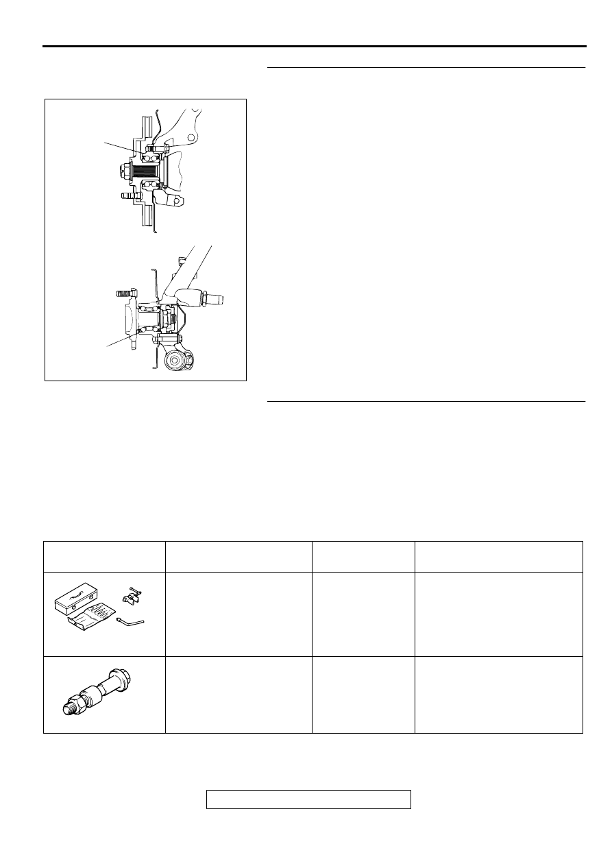
STEP 4. Check the wheel bearings for wear, damage or 
dryness.
Q: Is there fault?

YES : Apply grease or replace the part. Then go to Step 5.
NO :  Go to Step 5.

STEP 5. Recheck symptom.

Q: Is the symptom eliminated?

YES : Diagnosis is complete.
NO :  Start over at step 1. If a new symptom surfaces, refer 

to the symptom chart.

SPECIA L TO O LS

M1351000600081

AC000862

WHEEL
BEARING

WHEEL
BEARING

<FRONT>

<REAR>

AB

TOOL

TOOL NUMBER AND 
NAME

SUPERSESSION

APPLICATION

MB990964
Brake tool set
A: MB990520
Disc brake piston expander
B: MB990619
Installer

General service 
tool

Pushing-in of the disc brake 
piston

Installation of the drum brake 
wheel cylinder piston cup

MB990998
Front hub remover and 
installer

MB990998-01

Provisional holding of the wheel 
bearing

MB990964

A

B

MB990998

ON-VEHICLE SERVICE

TSB Revision

BASIC BRAKE SYSTEM

35A-18

O N -VEH IC LE SERVIC E

BRAKE PEDAL CHECK AND ADJUSTMENT

M1351000900082

BRAKE PEDAL HEIGHT

1. Turn up the carpet etc. under the brake pedal.
2. Measure the brake pedal height as illustrated. If it is not 

within the standard value, adjust as follows.

Standard value: 175 

 178 mm (6.9 

 7.0 inches) [From 

the surface of melting sheet (floorboard) to the face of 
pedal pad]

(1) Disconnect the stoplight switch connector.
(2) Rotate the stoplight switch 1/4 turn counter clockwise to 

loosen.

(3) Loosen the operating rod jam nut. Turn the serrations of 

the operating rod with pliers to adjust the brake pedal 
height to the standard value.

(4) Turn the stoplight switch until it contacts the stopper. 

During this step, secure the pedal by moving it forward by 
hand.

(5) Adjust the stoplight switch so that it has the specified 

clearance as shown. Turn the stoplight switch 1/4 turn 
clockwise to secure.

(6) Connect the connector of the stoplight switch.
(7) Check to be sure that the stoplight does not illuminated 

with the brake pedal released

3. Return the carpet, etc. to its original position.

BRAKE PEDAL FREE PLAY

1. Turn the ignition switch to the "LOCK" (OFF) position, 

depress the brake pedal two or three times. After eliminating 
the vacuum in the brake booster, press the pedal down by 
hand, and confirm that the amount of movement before 
resistance is met (free play) is within the standard value 
range.

Standard value: 3 

 8 mm (0.12 

 0.31 inch)

AC000864 AB

STOPLIGHT
SWITCH

OPERATING
ROD

OPERATING
ROD JAM NUT

AC000865

PEDAL DOWN

PEDAL UP

JAM NUT

AB

AC000866AB

STOPPER

0.5 

 1.5 mm

(0.02 

 0.06 in)

AC000867

ON-VEHICLE SERVICE

TSB Revision

BASIC BRAKE SYSTEM

35A-19

2. If the brake pedal play is not within the standard value, 

check the following, and adjust or replace if necessary:

Excessive play between the brake pedal and the clevis pin, 
or between the clevis pin and the brake booster operating 
rod

Brake pedal height

Installation position of the stoplight switch, etc.

CLEARANCE BETWEEN BRAKE PEDAL AND 
FLOORBOARD

1. Turn up the carpet etc. under the brake pedal.
2. Start the engine, depress the brake pedal with 

approximately 490 N (110 pound) of force, and measure the 
clearance between the brake pedal and the floorboard.

Standard value: 90 mm (3.5 inches) or more [From the 
surface of melting sheet (floorboard) to the face of 
pedal pad]

3. If the clearance is outside the standard value, check for air 

trapped in the brake line, thickness of the disc brake pad, 
clearance between the lining and the drum and dragging in 
the parking brake. And then adjust and replace defective 
parts as required.

4. Return the carpet etc. to its original position.

STOPLIGHT SWITCH CHECK

M1351008900105

1. Connect an ohmmeter between the stoplight switch 

connector terminals. 

2. There should be no continuity between the terminals when 

the plunger is pushed in as shown. There should be 
continuity when it is released.

AC000868

TESTER 
CONNECTION

PLUNGER

SPECIFIED 
CONDITION

 2

IN

Open circuit

OUT

Less than 2

ACX00671AB

NO CONTINUITY CONTINUITY

4 mm

(0.16 in)

ON-VEHICLE SERVICE

TSB Revision

BASIC BRAKE SYSTEM

35A-20

BRAKE BOOSTER OPERATING TEST

M1351001000071

1. For simple checking of the brake booster operation, carry 

out the following tests:

(1) Run the engine for one or two minutes, and then stop it. If 

the pedal depresses fully the first time but gradually 
becomes higher when depressed succeeding times, the 
booster is operating properly. If the pedal height remains 
unchanged, the booster is defective. Go to step 2.

(2) With the engine stopped, step on the brake pedal several 

times. Then step on the brake pedal and start the engine. 
If the pedal moves downward slightly, the booster is in 
good condition. If there is no change, the booster is 
defective. Go to step 3.

(3) With the engine running, step on the brake pedal and 

then stop the engine. Hold the pedal depressed for 30 
seconds. If the pedal height does not change, the booster 
is in good condition, if the pedal rises, the booster is 
defective.

2. If the above three tests are okay, the booster is OK. If one of 

the above three tests is not okay, the check valve, vacuum 
hose, or booster is defective. Check the check valve (Refer 
to 

P.35A-21

.), vacuum hose for leaks, high volume engine 

vacuum applied to booster. Repair or replace as necessary. 
If these are OK, replace booster and repeat this test starting 
at Step 1.

AC000870

GOOD

NO GOOD

AB

AC000871 AB

WHEN ENGINE
IS STOPPED

WHEN ENGINE
IS STARTED

AC000872

GOOD

NO GOOD

AB


Content   ..  565  566  567  568   ..