Mitsubishi Eclipse / Eclipse Spyder (2000-2002). Service and repair manual - part 478


  Index      Mitsubishi     Mitsubishi Eclipse / Eclipse Spyder (2000-2002). Service and repair manual


Search            


Content   ..  476  477  478  479   ..


Mitsubishi Eclipse / Eclipse Spyder (2000-2002). Service and repair manual - part 478


AUTOMATIC TRANSAXLE DIAGNOSIS

TSB Revision

AUTOMATIC TRANSAXLE

23A-204

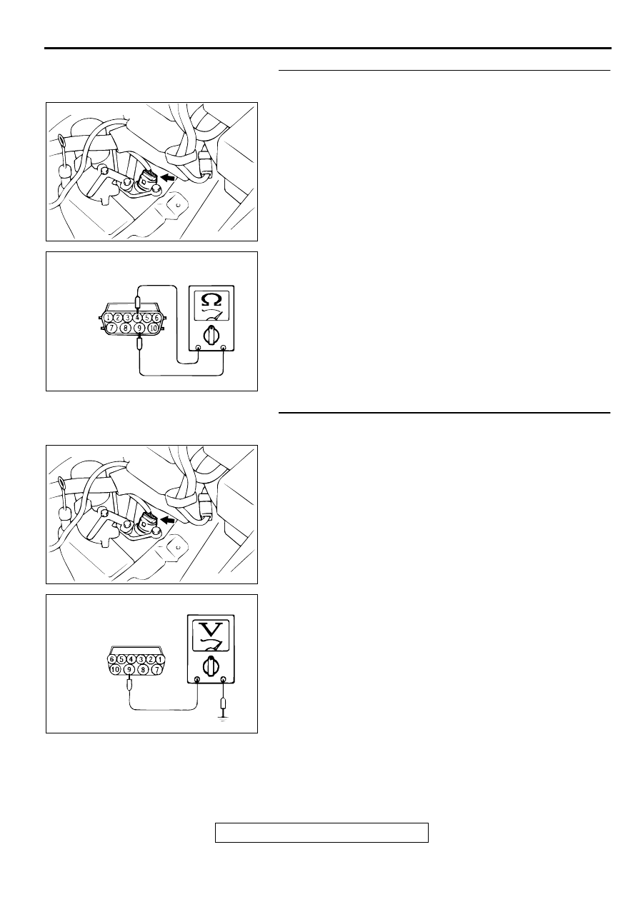
STEP 10. Check the second solenoid valve at solenoid 
valve assembly connector B-40.
(1) Disconnect connector B-40 and measure at the solenoid 

valve side.

(2) Measure the resistance between terminal 4 and 9.

Standard value: 2.7 - 3.4 

Q: Is the resistance at the standard value?

YES : Go to Step 11.
NO :  Replace the second solenoid valve. Refer to GROUP 

23B, Valve Body 

P.23B-69

.

STEP 11. Check the power supply voltage at solenoid 
valve assembly connector B-40.
(1) Disconnect connector B-40 and measure at the harness 

side.

(2) Turn the ignition switch to "ON" position.

(3) Measure the voltage between terminal 9 and ground.

Voltage should be battery positive voltage.

(4) Turn the ignition switch to "LOCK" (OFF) position.

Q: Is the voltage normal?

YES : Go to Step 13.
NO :  Go to Step 12.

ACX02479

CONNECTOR: B-40

AE

AC001964

HARNESS
CONNECTOR: B-40

AD

ACX02479

CONNECTOR: B-40

AE

AC001967

HARNESS
CONNECTOR: B-40

AD

AUTOMATIC TRANSAXLE DIAGNOSIS

TSB Revision

AUTOMATIC TRANSAXLE

23A-205

STEP 12. Check connector A-19X at A/T control relay for 
damage.
Q: Is the connector in good condition?

YES : Repair it because of harness open circuit or short 

circuit to ground between solenoid valve assembly 
connector B-40 terminal 9 and A/T control relay 
connector A-19X terminal 3.

NO :  Repair or replace it. Refer to GROUP 00E, Harness 

Connector Inspection 

P.00E-2

.

STEP 13. Check connectors C-61 <2.4L Engine> or C-63 
<3.0L Engine> at PCM connector for damage.
Q: Are the connectors in good condition?

YES : Go to Step 14.
NO :  Repair or replace it. Refer to GROUP 00E, Harness 

Connector Inspection 

P.00E-2

.

STEP 14. Check harness for open circuit, or short circuit to 
ground between solenoid valve assembly connector B-40 
terminal 4 and PCM connector C-61 <2.4L Engine> or C-63 
<3.0L Engine> terminal 106.
Q: Is the harness wire in good condition?

YES : Replace the PCM.
NO :  Repair it.

AC001655

CONNECTOR: A-19X

BATTERY

A/T CONTROL
RELAY

AD

AC001657

CONNECTOR: C-61 <2.4L ENGINE> OR
C-63 <3.0L ENGINE>

PCM

AN

ACX02479

CONNECTOR: B-40

AE

AC001657

CONNECTOR: C-61 <2.4L ENGINE> OR
C-63 <3.0L ENGINE>

PCM

AN

AUTOMATIC TRANSAXLE DIAGNOSIS

TSB Revision

AUTOMATIC TRANSAXLE

23A-206

DTC 34: Overdrive Solenoid Valve System

Solenoid Valve System Circuit
Refer to 

P.23A-185

.

CIRCUIT OPERATION
Refer to 

P.23A-185

.

DTC SET CONDITIONS
If the resistance value for a solenoid valve circuit is 
greater than 3.5 

 for 4 seconds at 100

°

C (212

°

F) or 

less than 2.6 

 for 4 seconds at 100

°

C (212

°

F), it is 

judged that there is a short circuit or an open circuit 
in the solenoid valve and the diagnostic trouble code 
number "34" is displayed. The transmission is locked 
into 3rd gear as a fail-safe measure, and the "N" 
range light flashes once per second.

TROUBLESHOOTING HINTS (The most likely 

causes for this code to be set:)

Malfunction of underdrive solenoid valve

Damaged harness, connector

Malfunction of the PCM

DIAGNOSIS

Required Special Tool:
MB991502: Scan Tool (MUT-II)

STEP 1. Using scan tool MB991502, read the A/T 
diagnostic trouble code.

CAUTION

To prevent damage to scan tool MB991502, always turn the 
ignition switch to "LOCK" (OFF) position before 
connecting or disconnecting scan tool MB991502.
(1) Connect scan tool MB991502 to the data link connector.
(2) Turn the ignition switch to "ON" position.
(3) Read the A/T diagnostic trouble code.
(4) Turn the ignition switch to "LOCK" (OFF) position.

Q: Is the A/T diagnostic trouble code number "54" output?

YES : Refer to 

P.23A-237

, code number 54: A/T control 

relay system.

NO :  Go to Step 2.

AC001252

MB991502

16 PIN

AB

AUTOMATIC TRANSAXLE DIAGNOSIS

TSB Revision

AUTOMATIC TRANSAXLE

23A-207

STEP 2. Using scan tool MB991502, check actuator test 
item 04: Overdrive Solenoid Valve.
(1) Connect scan tool MB991502 to the data link connector.
(2) Turn the ignition switch to "ON" position.
(3) Set scan tool MB991502 to actuator test mode for item 04, 

Overdrive Solenoid Valve.

An operation sound should be heard from solenoid 
valve when the overdrive solenoid valve is operated.

(4) Turn the ignition switch to "LOCK" (OFF) position.

Q: Is the solenoid valve operating properly?

YES : This malfunction can be intermittent. Refer to GROUP 

00, How to Use Troubleshooting/Inspection Service 
Points 

 How to Cope with Intermittent Malfunction 

P.00-6

.

NO :  Go to Step 3.

STEP 3. Check the solenoid valve output voltage at PCM 
connector C-61 <2.4L Engine> or C-63 <3.0L Engine> by 
backprobing.
(1) Do not disconnect connector C-61 <2.4L Engine> or C-63 

<3.0L Engine>.

(2) Turn the ignition switch to "ON" position.

(3) Measure the voltage between terminal 130 and ground by 

backprobing.

Voltage should be battery positive voltage.

(4) Turn the ignition switch to "LOCK" (OFF) position.

Q: Is the voltage normal?

YES : Go to Step 4.
NO :  Go to Step 9.

AC001252

MB991502

16 PIN

AB

AC001657

CONNECTOR: C-61 <2.4L ENGINE> OR
C-63 <3.0L ENGINE>

PCM

AN

AC001965

C-61 <2.4L ENGINE> OR
C-63 <3.0L ENGINE>
CONNECTOR HARNESS 
SIDE VIEW

AD


Content   ..  476  477  478  479   ..